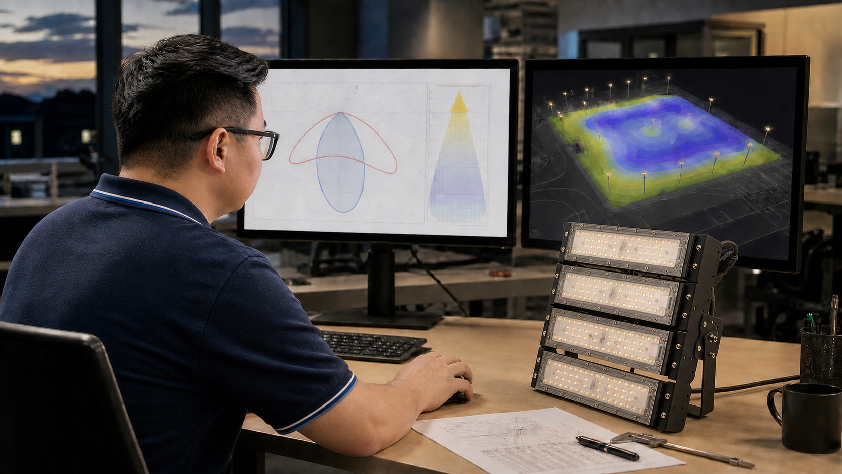
An IES or LDT file can import into lighting software without an error and still be the wrong file for the order. That is the procurement risk many project teams miss. The filename may show the correct housing, while the measured sample used a different wattage, LED, optic, front glass or drive current. The DIALux calculation can look professional, but its lux levels, uniformity and fixture quantity are only as reliable as the photometric data behind it.
For contractors and importers, the important question is not simply, “Can the manufacturer provide an IES file?” It is:
Can the manufacturer provide a traceable photometric file for the exact configuration being quoted and produced?
This guide explains the practical difference between IES and LDT files, what they can and cannot prove, how to review them before simulation and how to connect the approved file to the purchase order and production sample.
Important: A photometric file describes a measured or declared luminous-intensity distribution. It is not, by itself, proof of safety certification, ingress protection, lifetime, color quality or production consistency. These require separate documents and controls.
Quick Answer
- IES and LDT are data-transfer formats, not competing levels of quality. Either can support a professional calculation when the underlying photometry is correct.
- Request the raw
.iesor.ldtfile. A polar-curve screenshot or PDF report cannot be imported as equivalent calculation data. - Match the file to the complete luminaire configuration. Model, wattage, LED, drive current, optic, CCT/CRI option, cover and accessory can all matter.
- Check the imported data before calculating. Confirm lumens, power, dimensions, distribution, orientation and file identity.
- Freeze the approved file with the approved sample and purchase specification. If the bill of materials changes, require a photometric review before accepting the substitution.
1. What Is a Photometric File?
A luminaire photometric file is a machine-readable description of how luminous intensity is distributed in different directions around a tested or characterized light source.
Its most valuable content is not a rendered picture of a beam. It is the angular candela data that calculation software uses to estimate how much light reaches each point in a modeled space.
Depending on the format and the way the file was prepared, it may also contain or reference:
- luminaire and manufacturer identification;
- luminaire dimensions;
- lamp or light-source information;
- luminous flux;
- electrical power;
- photometric type and coordinate system;
- symmetry information;
- vertical and horizontal measurement angles;
- intensity values at those angles;
- test or laboratory references;
- tilt information or multipliers.
The Illuminating Engineering Society lists ANSI/IES LM-63-19 as its standard file format for the electronic transfer of photometric data and related information. DIALux, meanwhile, supports local luminaire files including IES and LDT for project calculations.
Technical references:
What the file does not automatically prove
Opening successfully does not confirm that:
- the test sample matches the current production bill of materials;
- the luminaire uses the quoted LED brand or bin;
- the CCT and CRI match the order;
- the driver current matches the production setting;
- the product has passed an IP, IK, EMC, safety or salt-spray test;
- the light output will be maintained throughout life;
- the filename and internal data have not been edited or copied from another model.
A photometric file is essential project data, but it still needs configuration control.
2. IES vs. LDT: The Practical Difference
The choice between IES and LDT is often driven by market practice, consultant preference and software workflow. It should not be treated as a shortcut for judging measurement quality.
| Comparison point | IES file | LDT file |
|---|---|---|
| Common name | IES photometric file | EULUMDAT file |
| Extension | .ies |
.ldt |
| Standard or convention | ANSI/IES LM-63 family | EULUMDAT data format |
| Common market use | Widely requested internationally and especially familiar in North American specifications | Common in European lighting workflows |
| File structure | Plain-text fields, angles and candela values defined by the applicable LM-63 version | Plain-text data in a fixed sequence for luminaire, lamp, dimensions and intensity information |
| Typical use | Transfer photometry into DIALux, AGi32 and other compatible tools | Transfer photometry into DIALux and other compatible European lighting tools |
| Main buyer question | Does the file represent the exact configuration? | Does the file represent the exact configuration? |
DIAL describes EULUMDAT .ldt files as pure-text files containing basic lighting-design data such as luminaire dimensions, lamp configuration and luminous intensity. Its free LDT Editor can open both LDT and IES files and saves edited data as EULUMDAT.
Reference: DIALux LDT Editor
Converting the format does not improve the measurement
An IES file converted to LDT does not become more accurate because the extension changed. Conversion can make the data compatible with a preferred workflow, but it cannot correct:
- an incorrect test sample;
- missing angles;
- a wrong intensity multiplier;
- a mismatched optic;
- inaccurate luminaire dimensions;
- poor measurement practice;
- a renamed file copied from another product.
Evaluate the source and configuration, not only the extension.
3. How DIALux Uses the File
Lighting software combines the photometric distribution with the project model.
The file supplies the luminaire’s directional light data. The designer then adds the variables that belong to the project:
- room, facade, plaza or landscape geometry;
- mounting position and photometric center height;
- luminaire rotation, tilt and aiming point;
- calculation surfaces and grids;
- target average, minimum and maximum illuminance;
- uniformity criteria;
- material reflectance;
- obstructions, furniture, trees and architectural elements;
- maintenance factor;
- dimming level and lighting scene.
DIALux states that luminaires can be imported from local IES and LDT files, positioned and rotated, and evaluated with results such as isolines, value charts, false-color renderings, illuminance, uniformity and glare-related assessments.
Reference: DIALux outdoor-lighting workflow
This leads to an important distinction:
The photometric file describes the luminaire distribution. The DIALux project describes how that distribution is applied.
A correct file in an incorrect model produces an incorrect result. A correct model using the wrong file does the same.
4. Match the File to the Exact Luminaire Configuration
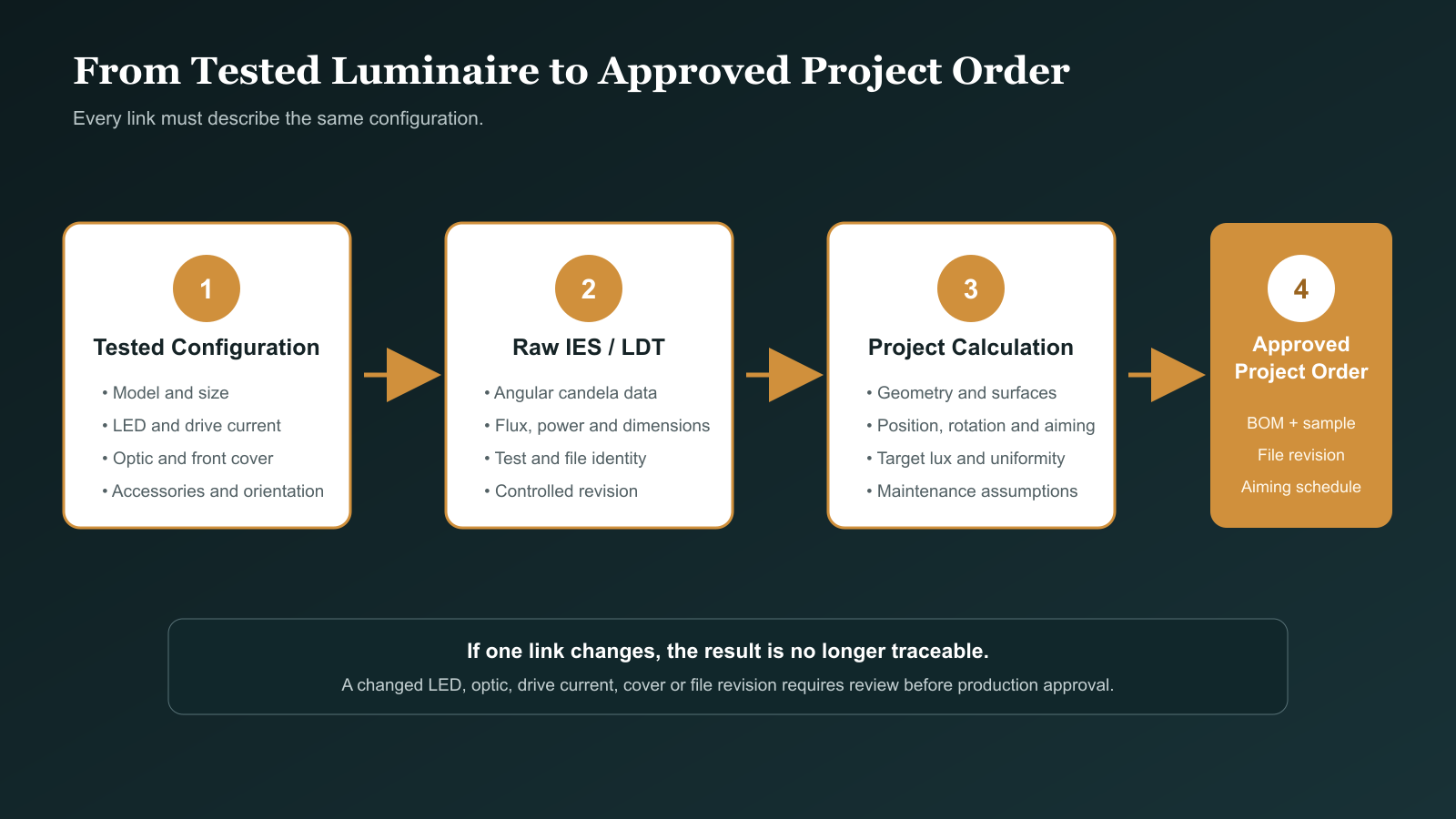
The product family name is not enough.
Many LED luminaire platforms use one housing with several optical and electrical combinations. A single product family may include:
- several wattages;
- different COB or SMD packages;
- multiple drive currents;
- reflector and TIR-lens versions;
- narrow, medium, wide and asymmetric distributions;
- clear, frosted or patterned front glass;
- snoots, honeycombs or anti-glare accessories;
- CRI 80, CRI 90 or application-specific LED options;
- different CCTs or tunable/color-changing versions.
Each change must be assessed for photometric impact.
| Configuration field | Why it matters to the file |
|---|---|
| Exact model and size | Different housings or apertures can change geometry and optical control |
| Nominal wattage | Often corresponds to a different LED package, board or drive current |
| Actual drive current | Changes output and can change thermal operating conditions |
| LED manufacturer and package | Source size and emitting-surface geometry influence optic performance |
| CCT and CRI | Higher-CRI or different-CCT LEDs may not deliver the same lumens |
| Reflector or lens code | Directly determines the intensity distribution |
| Front cover | Frosted or textured covers can widen the beam and reduce peak intensity |
| Shield, louver or snoot | Can reduce spill, output and viewing-angle brightness |
| Emergency or control mode | May operate the luminaire at a reduced output |
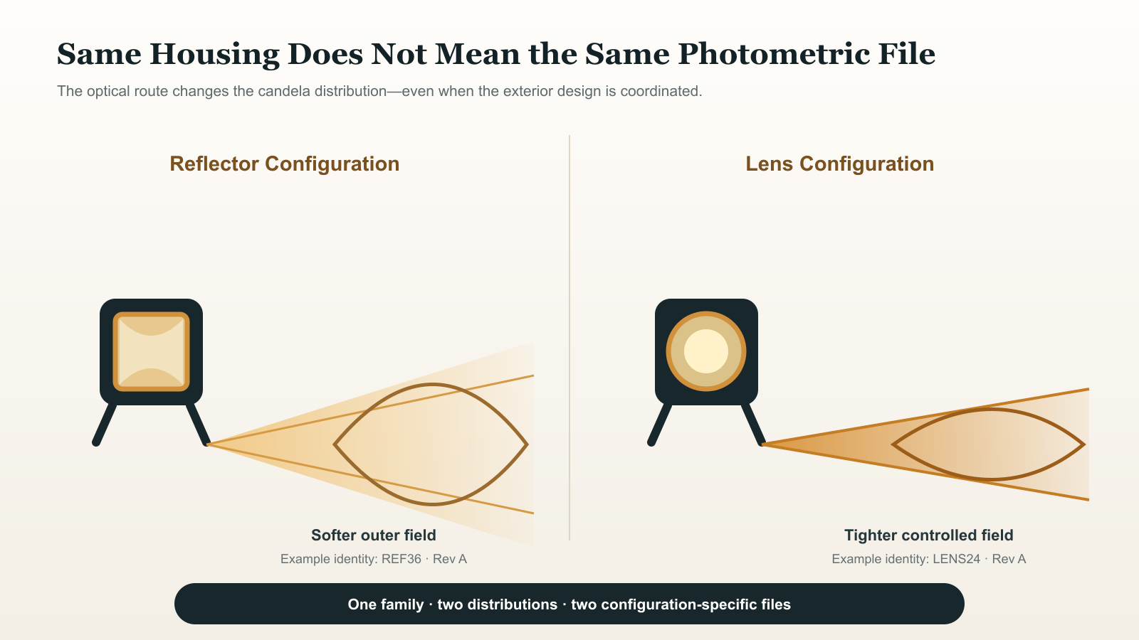
Same housing does not mean same photometry
Synno’s SL-FL-F1A private-mold landscape spotlight family is produced with both reflector and lens optical routes. A reflector version and a lens version can share a coordinated exterior design while creating different center intensity, field transition and spill characteristics.
The correct procedure is to assign a separate photometric identity to each approved optical configuration. An IES file for a 12W lens version must not be renamed and used for a 12W reflector version merely because the housing looks the same.
5. Use a Traceable File Name and Configuration Sheet
A useful filename should help the buyer and designer identify the file without opening several versions.
One practical pattern is:
Model_Size_Wattage_CCT_CRI_Optic_Cover_Revision.ies
Illustrative example:
SL-FL-F1A_M_12W_3000K_CRI90_LENS24_CLEAR_RevA.ies
The filename is only an index. It should be supported by a configuration sheet containing:
- product model and size;
- tested sample number;
- test date and laboratory or equipment reference;
- LED brand, package, CCT and CRI;
- LED quantity and drive current;
- driver model or electrical setting;
- optic type and optic code;
- front cover and optical accessories;
- measured luminaire lumens and input power;
- file revision and approval status.
For customized OEM/ODM versions, include the customer project code or BOM revision so the file cannot be confused with the standard configuration.
6. Ten Checks Before You Use an IES or LDT File
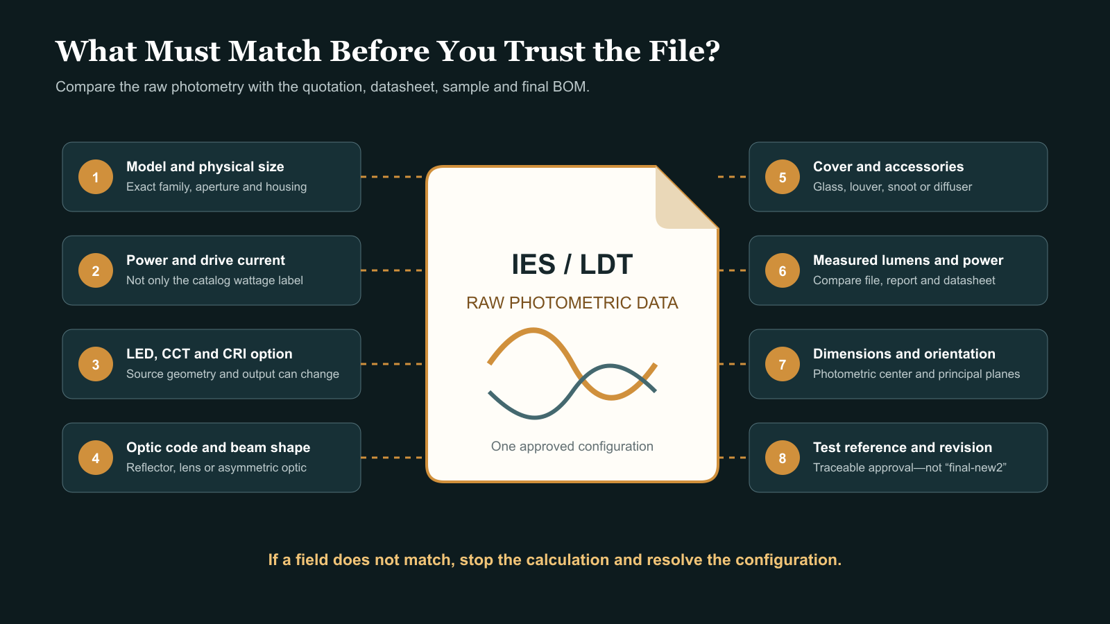
1. Confirm the model identity
Compare the internal luminaire description, filename, datasheet and quotation. A similar family name is not sufficient.
2. Compare luminaire lumens
The imported flux should be reasonably consistent with the approved photometric report or configuration datasheet. If the file shows substantially different output, stop and ask why.
3. Compare input power
Power is not the basis of the distribution, but a mismatch can reveal that the file belongs to another electrical configuration.
4. Check the physical dimensions
Incorrect length, width or height can place the photometric center incorrectly, create collisions in a model or confuse fixture schedules.
5. Review the polar curve
Does the distribution visually match the requested optic: narrow, medium, wide, wall-wash or asymmetric? A 15° spotlight should not import as a broad diffuse distribution.
6. Check both photometric planes
For asymmetric luminaires, compare the principal planes. A 70° × 140° distribution can be rotated incorrectly if the luminaire orientation is misunderstood.
7. Verify beam and field information
If the datasheet states a beam angle, confirm it is consistent with the candela distribution. Remember that beam angle normally refers to the 50% intensity directions; it is not the complete visible field.
8. Confirm the file multiplier has not been used as an unexplained correction
Scaling a file to a new lumen value can be useful for a documented preliminary study, but it does not prove that a different LED, current or optic behaves identically.
9. Check orientation in a simple test scene
Place one luminaire above or in front of a flat calculation surface. Rotate it deliberately and confirm that the distribution moves in the expected direction before building the complete project.
10. Record the approved revision
Do not let final.ies, final-new.ies and final-new2.ies circulate across the design, sales and production teams. Use a controlled revision and approval date.
7. A File Can Be Numerically Valid but Commercially Wrong
Several common shortcuts create this problem.
A generic file is sent for the whole product family
The file may be a real test, but only for one wattage and optic. It cannot represent every configuration in the catalog.
The file is scaled to match a new lumen claim
Software can modify luminous flux. This may be acceptable for an explicitly labeled concept calculation when only output changes proportionally. It is risky when the source size, optic, cover or thermal condition also changes.
The filename is changed but the internal data is not
Buyers may only see the external filename. Open the file in a viewer and compare its internal luminaire fields.
A competitor or component-supplier file is used
A lens supplier’s theoretical distribution or a similar market product may help early optical development. It is not a substitute for finished-luminaire photometry.
A PDF curve is supplied instead of raw data
A PDF can support human review, but the project designer still needs the machine-readable file.
Production changes after approval
Changing the LED board, drive current, lens supplier, reflector finish, glass or accessory after simulation can invalidate the approved result even if the exterior housing is unchanged.
8. What the DIALux Report Should Show
A polished rendering is not enough to approve a project.
Request a calculation package that identifies:
| Required output | Why the buyer needs it |
|---|---|
| Project assumptions | Defines geometry, reflectance, maintenance factor and operating conditions |
| Luminaire schedule | Links model, quantity, wattage and optic to the layout |
| Photometric filename/revision | Shows which IES/LDT data produced the result |
| Position and aiming schedule | Lets the installer reproduce the calculation |
| Calculation grid or surfaces | Shows where lux values were assessed |
| Average, minimum and maximum values | Prevents approval from being based on one bright point |
| Uniformity | Reveals dark zones hidden by the average |
| Isolux or value chart | Shows distribution across the target area |
| False-color view | Makes coverage patterns easy to review, but should be read with numerical results |
| Glare or spill assessment | Important near roads, windows, neighboring property and pedestrian sightlines |
| Connected load | Supports electrical planning and energy review |
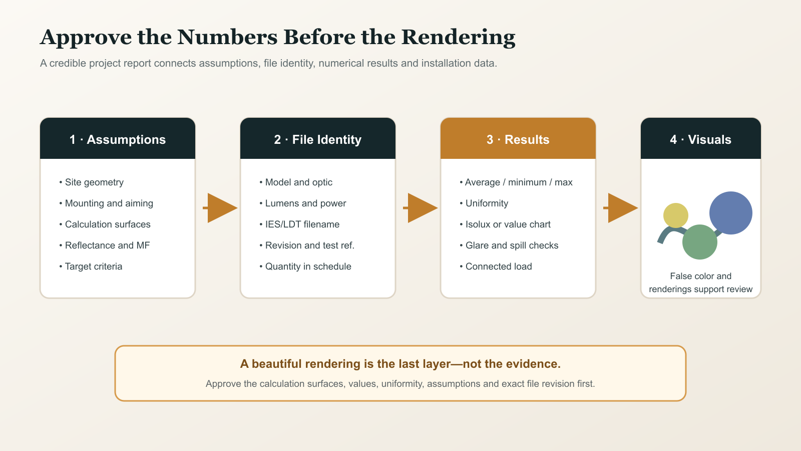
For adjustable flood lights and landscape spotlights, the aiming schedule is particularly important. A small change in tilt or rotation can move the highest-intensity region away from the intended target.
9. What to Send the Manufacturer Before Requesting Files
“Please send IES” is too vague when the product has multiple options.
Send:
- product model or shortlisted family;
- size and wattage;
- required CCT and CRI;
- input voltage and control method;
- required beam angle or distribution;
- reflector/lens preference if already selected;
- front glass and anti-glare accessories;
- mounting method and target orientation;
- project drawing and target lux/uniformity where calculation support is needed;
- required file format: IES, LDT or both;
- destination-market tender or documentation requirements;
- deadline and project revision.
If the final optic has not been selected, ask the manufacturer to provide clearly labeled candidate files rather than one generic file.
10. Recommended Approval Workflow for Bulk Orders
Step 1: Define the configuration
Create a line-item specification covering LED, driver, optic, cover, CCT, CRI, power and accessories.
Step 2: Receive the photometric package
Obtain the raw IES/LDT file, supporting photometric report or datasheet and configuration record.
Step 3: Run a one-luminaire check
Open the file, inspect its metadata and distribution, and test orientation on a simple surface.
Step 4: Complete the project calculation
Model the actual site, mounting positions, aiming, calculation grids, maintenance and required results.
Step 5: Approve a physical sample
Compare the sample at a controlled distance and aiming angle. For critical projects, measure illuminance at agreed points and record camera settings for beam photographs.
Step 6: Freeze the data
Attach the approved model configuration, photometric filename, file revision and sample code to the purchase specification.
Step 7: Control production changes
Require written review before substituting the LED, optic, driver current, glass or accessory. Decide whether the change requires new testing or a revised calculation.
11. An RFQ Paragraph You Can Copy
Please provide the raw IES and/or LDT photometric file for the exact luminaire configuration quoted. The file must match the stated model, size, wattage, LED package, drive current, CCT, CRI, optic code, front cover and accessories. Please also provide the measured luminaire lumens, input power, test or sample reference, test date and file revision. Do not provide a generic family file or a file scaled from another optic without written explanation. The approved photometric filename and revision will be referenced in the project calculation and purchase specification.
12. How This Applies to Synno Project Support
Synno manufactures indoor and outdoor LED luminaires with multiple wattages, optical systems, CCT/CRI choices, voltage options and project accessories. This flexibility is useful for contractors and importers, but it also makes configuration-specific documentation essential.
For a useful request, send the Synno technical team:
- the product family and required configuration;
- a drawing or dimensioned project plan;
- mounting positions and aiming restrictions;
- target lux and uniformity;
- destination-market requirements;
- the required IES/LDT files and DIALux outputs.
The technical review should connect the selected optic and electrical configuration to the calculation file. Where a private-mold family provides more than one optical route, each approved route should retain its own photometric identity.
Frequently Asked Questions
Is an IES file better than an LDT file?
Not inherently. Both can transfer luminaire photometric data into compatible lighting software. Accuracy depends on the source measurement, file preparation and whether the data matches the ordered configuration.
Can DIALux open both IES and LDT files?
Yes. DIALux documents local luminaire import using formats including IES and LDT. Its LDT Editor can also open IES and LDT files for reviewing basic data.
Does an IES file include CRI and CCT?
Files may contain descriptive information, but conventional photometric data is mainly used to describe luminous intensity distribution. Confirm color and spectral performance through the configuration datasheet and appropriate colorimetric test data rather than assuming the photometric file proves it.
Can I use one IES file for different wattages?
Only as a clearly identified preliminary assumption when the manufacturer or designer has justified the scaling method. For final approval, request data for the actual wattage, LED, current and optic configuration.
Can I rename an IES file for my project?
You can use a controlled project filename, but preserve the original file, internal identification, source and revision record. Renaming must not imply that an untested configuration was measured.
Why does the beam in DIALux look different from the site?
Possible causes include the wrong file, incorrect orientation or aiming, different mounting geometry, changed optics, surface reflectance, maintenance settings, obstructions, dimming, production variation or unrealistic visualization exposure.
Is a DIALux rendering proof that the lux requirement is met?
No. Review the numerical calculation surfaces, average and minimum values, uniformity, assumptions and luminaire/file schedule. A visually attractive rendering can hide an incorrect data source or weak calculation setup.
When should new photometric testing be requested?
Request a review when changes affect source geometry, drive current, optic, reflector finish, front glass, shielding or other components likely to change output or distribution. Critical tender and custom configurations may justify a new finished-luminaire test.
Conclusion
IES and LDT files turn a catalog selection into calculable project data, but the extension alone does not make the result tru