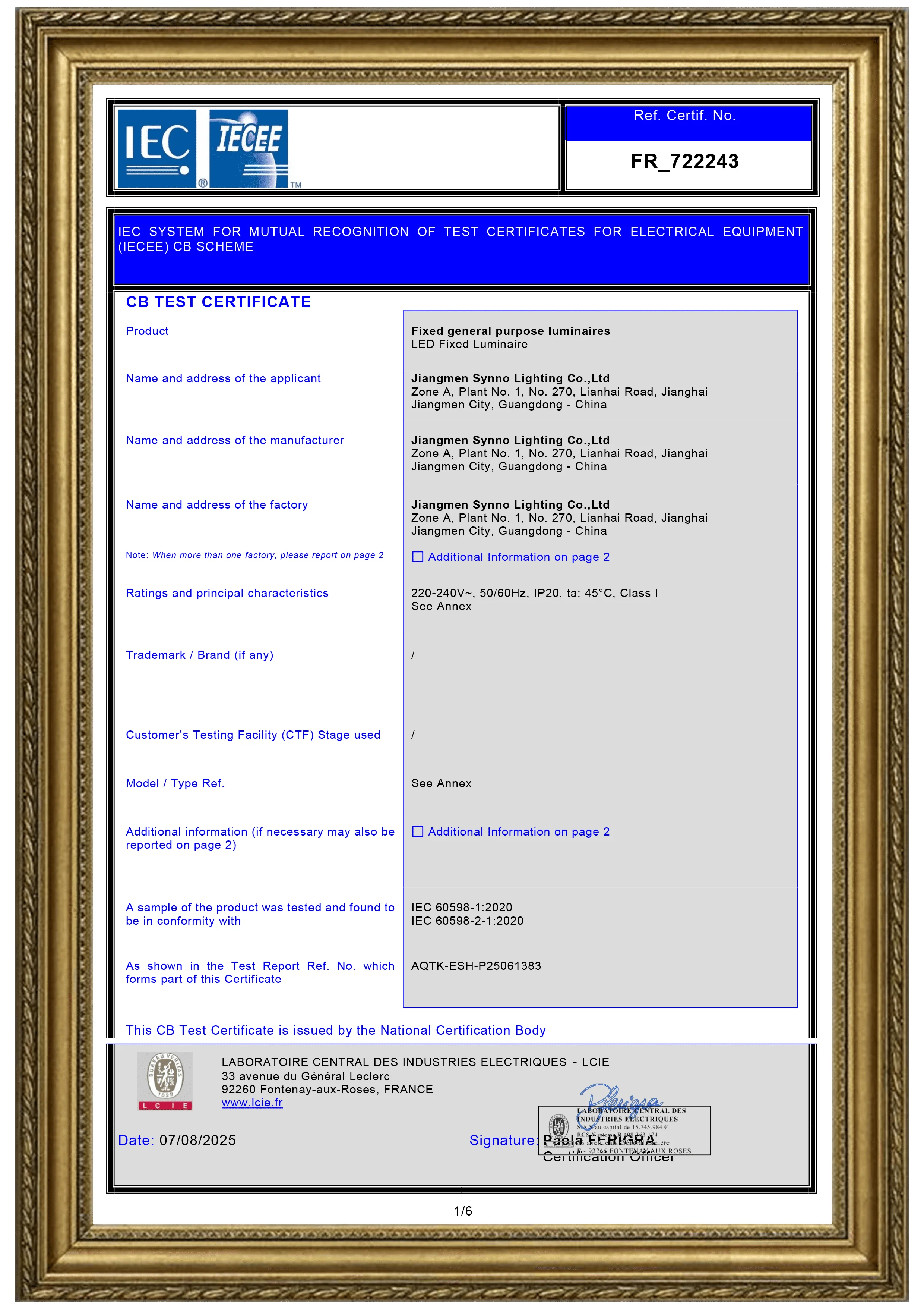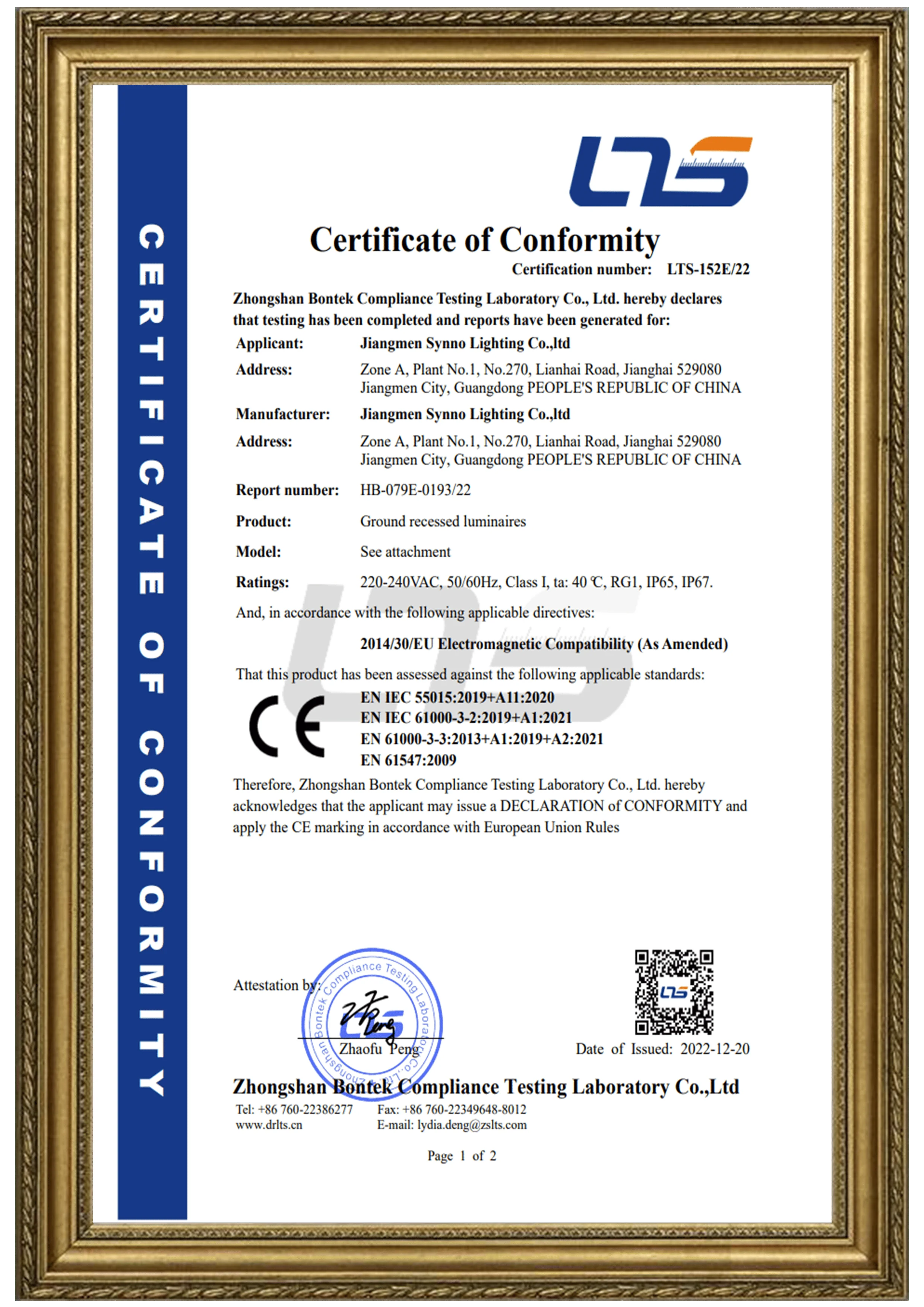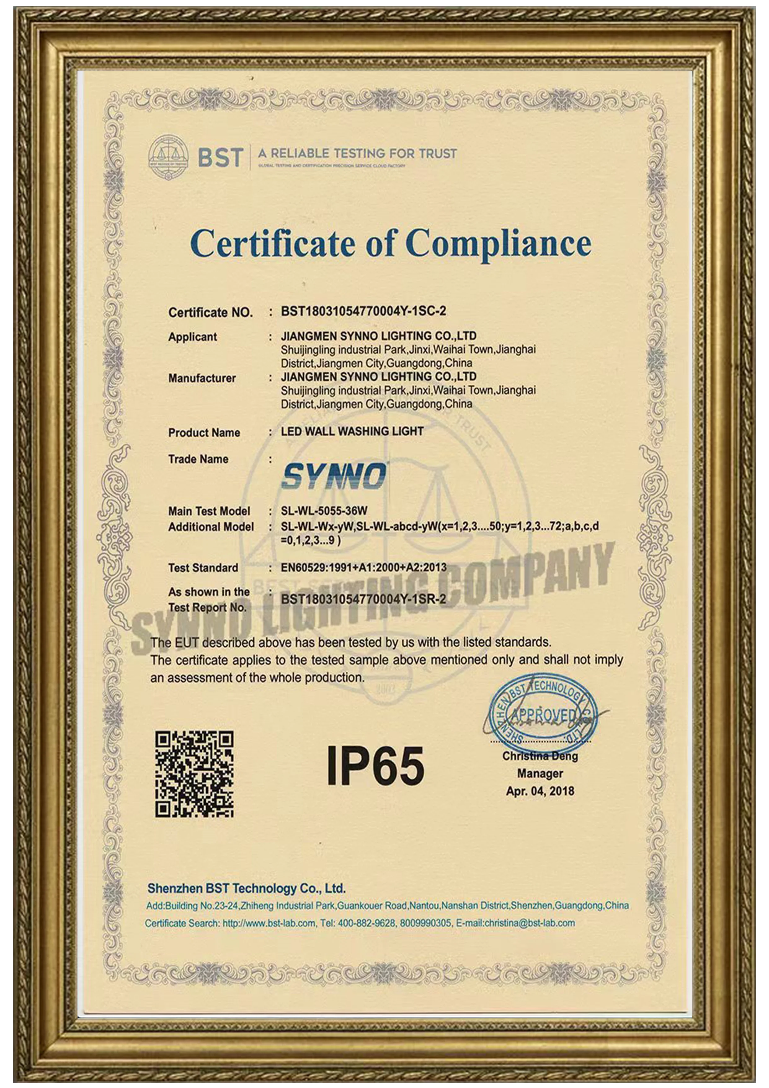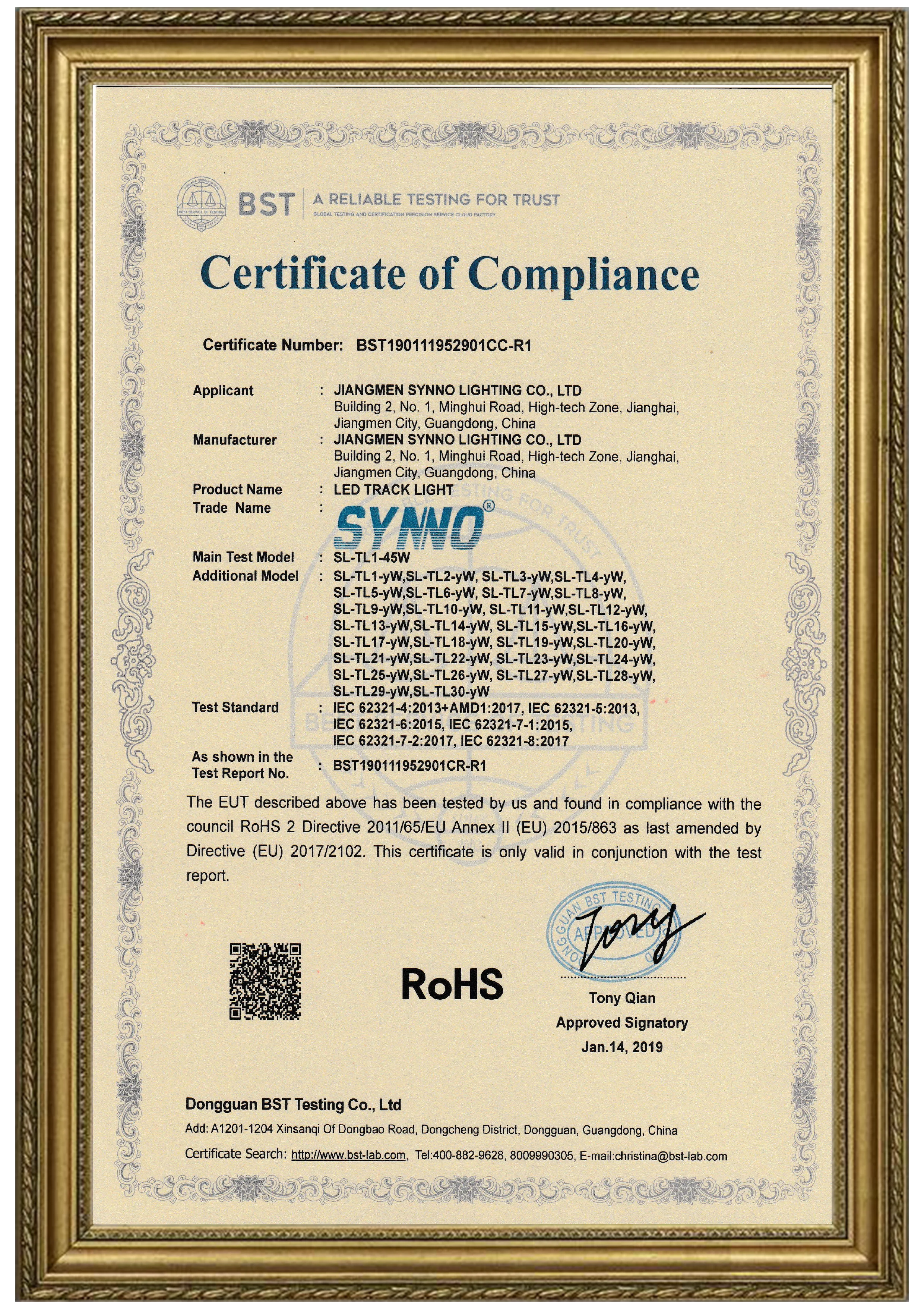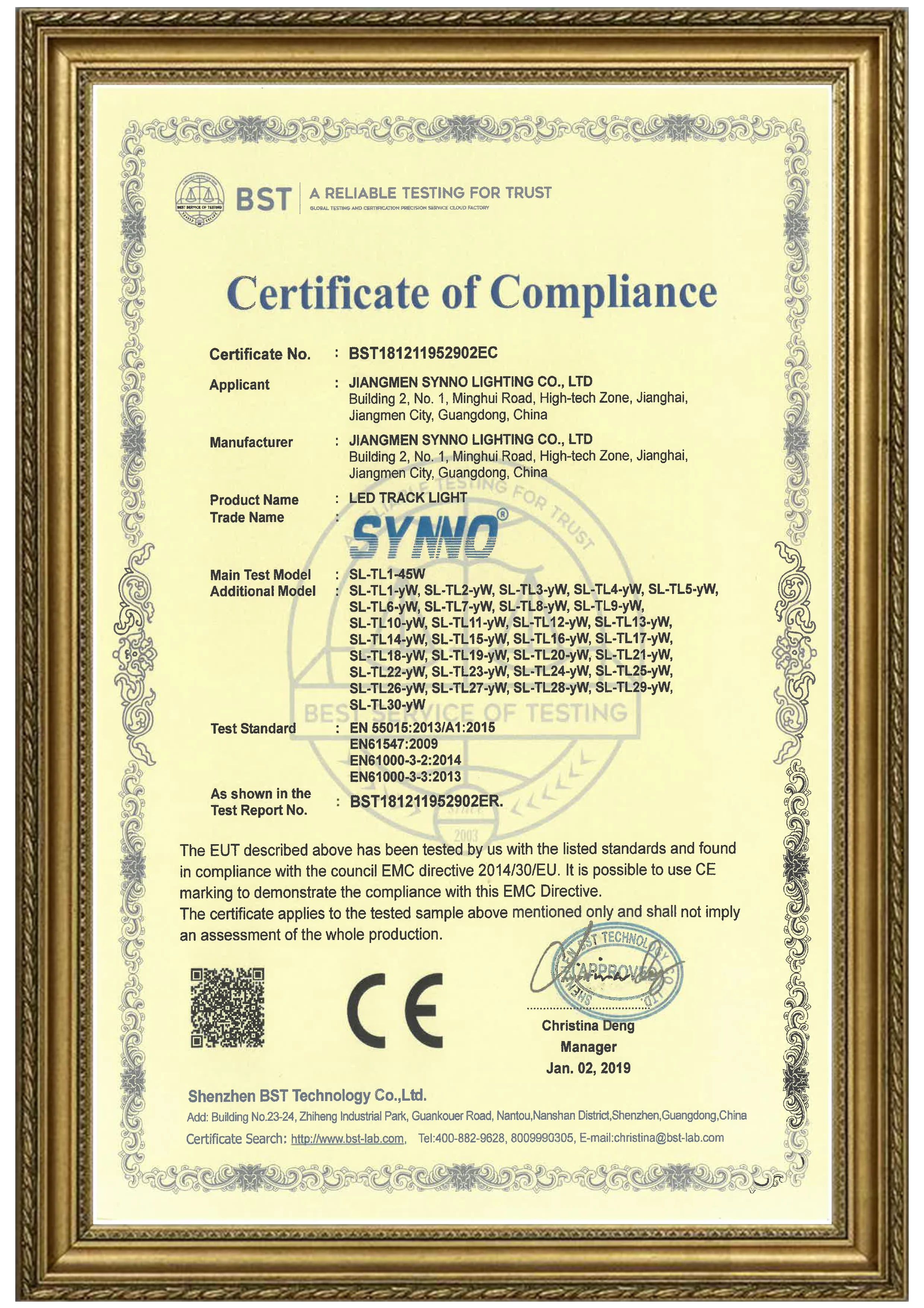
That statement is not a contradiction. The test result describes how one defined luminaire configuration behaved under a defined laboratory impulse. A completed lighting installation includes much more: the supply origin, distribution boards, cable routes, protective conductors, earthing system, control lines, external lightning exposure and every connection between the surge protective device and the equipment.
This distinction matters in hotels, villa compounds, parks, façades and parking areas. Long outdoor branches connect many electronic LED drivers across exposed parts of a site. If several drivers fail after the same weather event, replacing the luminaires without reviewing the electrical system may only reset the clock for the next failure.
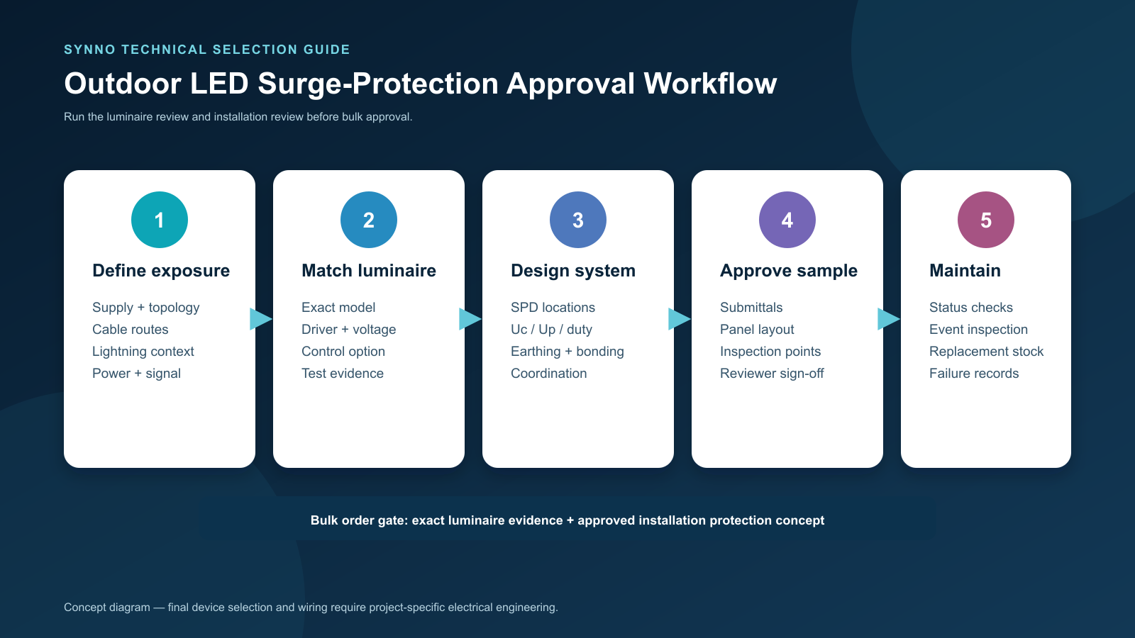
A better approach uses coordinated layers. First verify the immunity of the exact luminaire being purchased. Then design the installation-level surge protective devices, bonding, earthing and cable layout for the actual site. Finally, keep enough documentation to maintain those protective measures throughout the project life.
This guide explains what contractors and lighting buyers should request—and which decisions must remain with a qualified electrical designer under the applicable national rules.
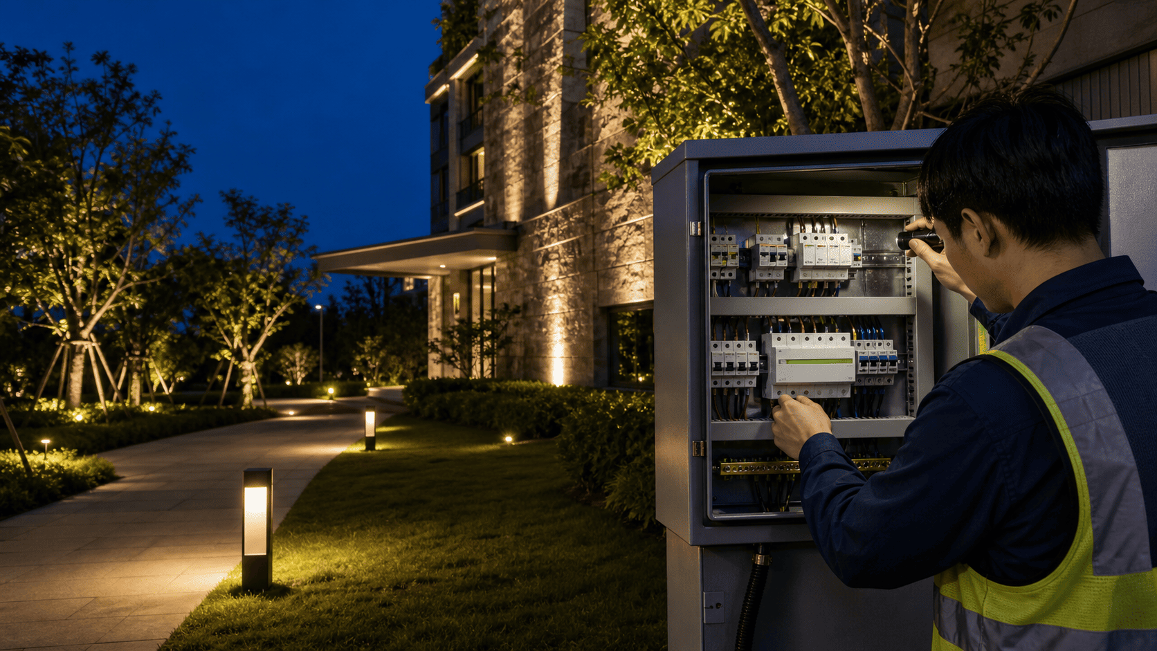
Important: This article is a procurement and coordination guide, not a wiring instruction. SPD selection, protective-device coordination, earthing and lightning-protection work must be designed and installed by qualified professionals in accordance with the local electrical code and the site's lightning-risk assessment.
Quick Answer
- A luminaire's 2 kV, 4 kV or 6 kV surge statement is not a complete lightning-protection design. Ask which exact model was tested, to which standard, with which coupling modes, polarities, ports, criteria and driver configuration.
- IEC 61000-4-5 describes a surge-immunity test for switching and lightning-related transients. Its scope does not cover direct lightning-current injection.
- An SPD limits transient voltage and diverts surge current. Its type and location must match the exposure, supply system and protection concept; one device cannot automatically protect every remote luminaire.
- The short conductors between an SPD and the circuit matter. Their inductive voltage contributes to the voltage that protected equipment may experience.
- Earthing and equipotential bonding are part of the current path, not optional accessories to the SPD.
- Long outdoor power and control cables require project-level review. Protection may be needed at boundaries, remote equipment or both ends of exposed lines, depending on the design.
- AC mains, 24 V DC lighting and DALI, 0–10 V or DMX control lines need devices selected for their own circuit characteristics. A power SPD is not a signal-line protector.
1. Start with the Failure Event, Not the Burnt Driver
Not every high-voltage problem is the same. A useful site investigation separates at least three categories.
Short transient overvoltage
A surge is a brief high-energy event associated with phenomena such as nearby lightning activity or electrical switching. It may enter through the supply, be induced into a cable, or appear as a difference in potential between connected parts of the installation.
Temporary or sustained overvoltage
A neutral fault, incorrect supply, wiring error or other power-quality problem can last much longer than a surge impulse. An SPD selected for short transients is not automatically a remedy for a sustained abnormal voltage. The supply fault must be identified and corrected.
Thermal, moisture or connection failure
An overheated driver, water-contaminated joint or loose terminal can resemble surge damage after the event. Moisture ingress and poor heat dissipation need their own diagnosis. Review Synno's guide to outdoor LED condensation when fogging, corrosion or wet joints are present.
Useful evidence includes the failure time, weather and switching records, affected circuits, distribution-board status, SPD indicator, supply measurements, insulation test results and photographs of each failed component. A cluster of failures on one remote branch tells a different story from one water-filled fitting.
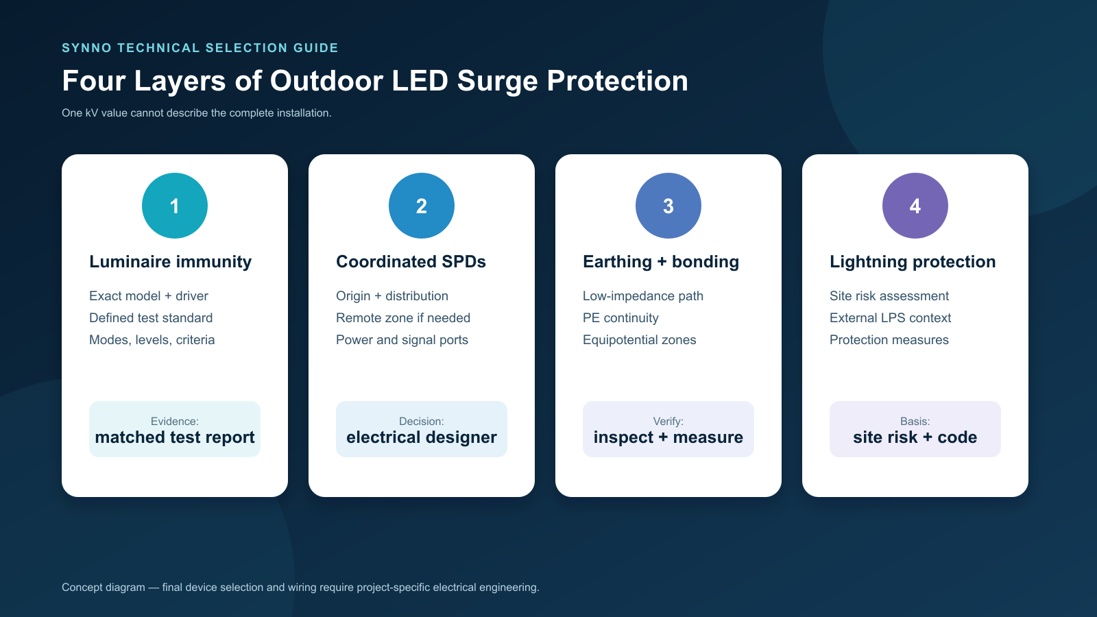
2. Four Protection Layers Answer Four Different Questions
The project team should avoid compressing the whole subject into one datasheet line.
| Layer | Main question | Typical evidence or decision owner |
|---|---|---|
| Luminaire immunity | What defined transient can this exact luminaire configuration tolerate in a laboratory test? | Test report or declaration tied to model, driver, voltage and construction |
| Installation SPDs | Where should surge voltage be limited and surge current diverted in this electrical system? | Electrical design, SPD selection data, coordination and installation record |
| Earthing and bonding | Is there a short, reliable equipotential path for diverted current? | Site drawings, measurements, inspection and local-code compliance |
| Lightning protection | What is the site's lightning risk and what structural/system measures are required? | Risk assessment and lightning-protection design |
The official scope of IEC 61000-4-5 covers immunity requirements, test levels, equipment and procedures for surges caused by switching and lightning transients. It expressly does not address direct lightning-current injection. For general lighting equipment, IEC 61547:2020 gives electromagnetic-immunity requirements; its 2020 edition increased surge and electrostatic-discharge test levels for road and street lighting equipment.
Installation-level SPD requirements are a different subject. IEC 61643-11:2025 covers low-voltage SPDs connected to AC power systems, while IEC 61643-12:2020 describes selection, operation, location and coordination principles. Lightning-risk management is addressed by IEC 62305-2:2024, and surge-protection measures for electrical and electronic systems within structures by IEC 62305-4:2024.
3. What Does a 2 kV, 4 kV or 6 kV Luminaire Claim Really Mean?
The number is useful only with context.
A complete test statement should identify:
- the exact luminaire and driver part number;
- rated input voltage and frequency;
- the referenced standard and edition;
- the ports and coupling paths tested;
- line-to-line and line-to-earth test levels where applicable;
- positive and negative polarities and number of impulses;
- performance criteria during and after the test;
- any external protection used in the test setup;
- whether the sample was Class I, Class II or a low-voltage configuration.
Two products advertised as “4 kV” may not represent the same test configuration. A higher number also does not repair a poor installation or prove survival of a direct strike.
For a bulk order, ask the supplier to map the report to the full order code. Changing the driver, dimming interface, wiring class or input voltage can change the relevant electrical configuration. If the evidence represents only a component, do not automatically present it as a test result for the complete luminaire.
4. Type 1, Type 2 and Type 3 SPDs Are Not a Good-Better-Best Ladder
The types describe test duties and intended positions within a coordinated protection concept. They are not three quality grades to be chosen only by the largest printed current value.
- Type 1 devices are associated with lightning-current duty at the origin of an installation where that duty is expected by the protection design.
- Type 2 devices limit transient overvoltages in distribution systems and are widely used at distribution-board level.
- Type 3 devices provide fine protection near sensitive equipment and are normally coordinated with upstream protection rather than used alone as the whole solution.
Combined devices also exist. The correct arrangement depends on factors such as the external lightning-protection system, overhead or underground supply, lightning-risk assessment, distribution topology, earthing arrangement, equipment withstand level and national regulations.
Therefore, “add one Type 2 SPD somewhere in the panel” is not a design specification. The engineer should document the selected device, connection mode, location, backup protection, coordination and end-of-life indication.
5. Read the SPD Datasheet as a System Document
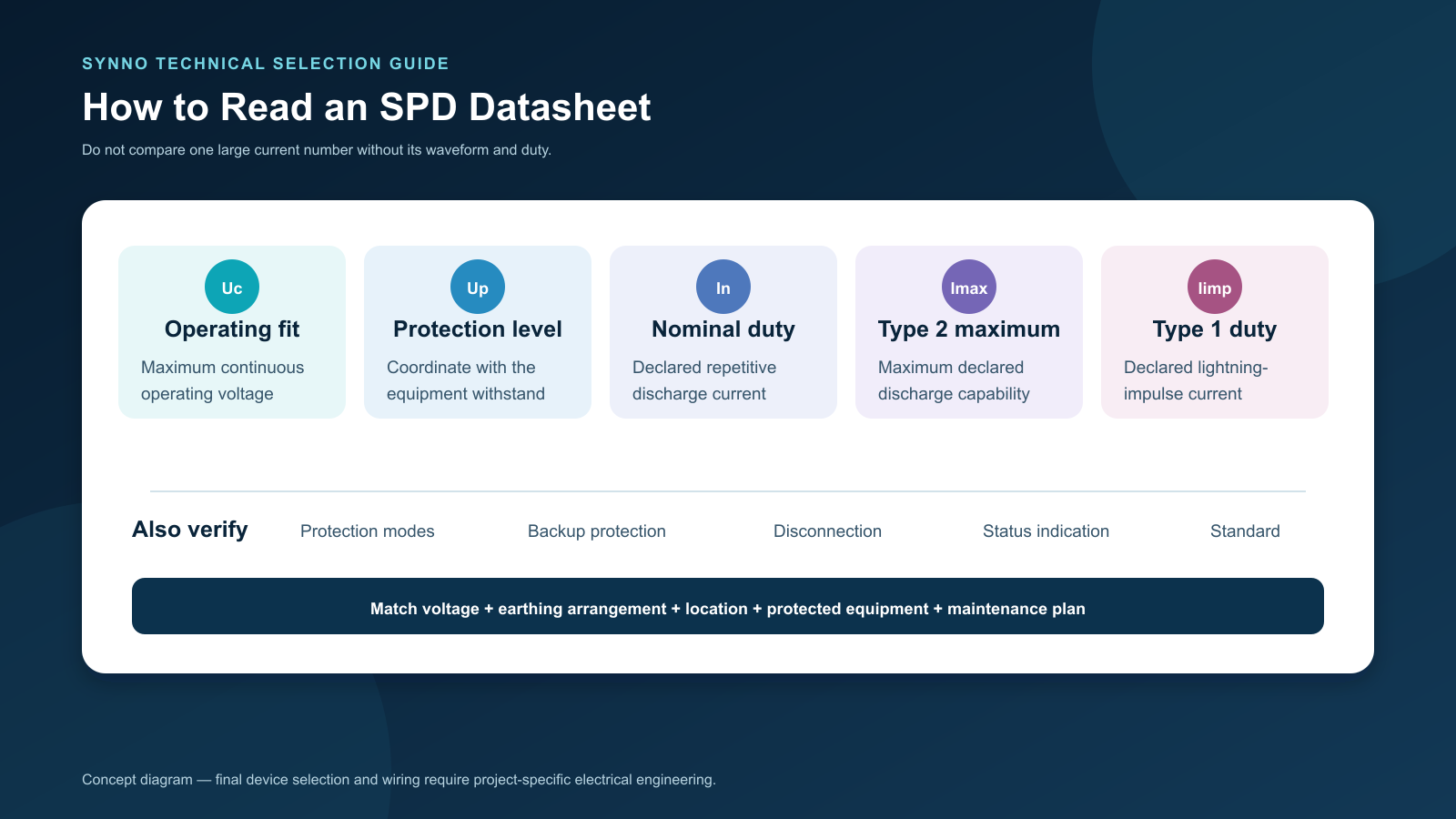
The following parameters have different meanings and should not be mixed:
| Parameter | Practical buyer question |
|---|---|
| Uc — maximum continuous operating voltage | Is the SPD compatible with the actual circuit voltage and earthing arrangement during normal operation? |
| Up — voltage protection level | Is the protection level, including installation effects, suitable for the equipment being protected? |
| In — nominal discharge current | What defined repetitive discharge duty is declared for the device? |
| Imax — maximum discharge current | What maximum Type 2 discharge capability is declared under the specified waveform? |
| Iimp — impulse current | What Type 1 lightning-current duty is declared under the specified waveform? |
| Modes of protection | Which conductor combinations are protected for the supply system? |
| Disconnector and backup protection | How is the SPD safely disconnected or protected at end of life or under fault conditions? |
| Status indication / remote contact | How will maintenance staff know that protection is no longer available? |
Values should be compared only when the standards, waveforms and test conditions match. The lowest Up is not automatically the correct choice if Uc, follow-current behaviour, supply arrangement or short-circuit coordination is wrong.
6. Long Cable Runs Change the Protection Problem
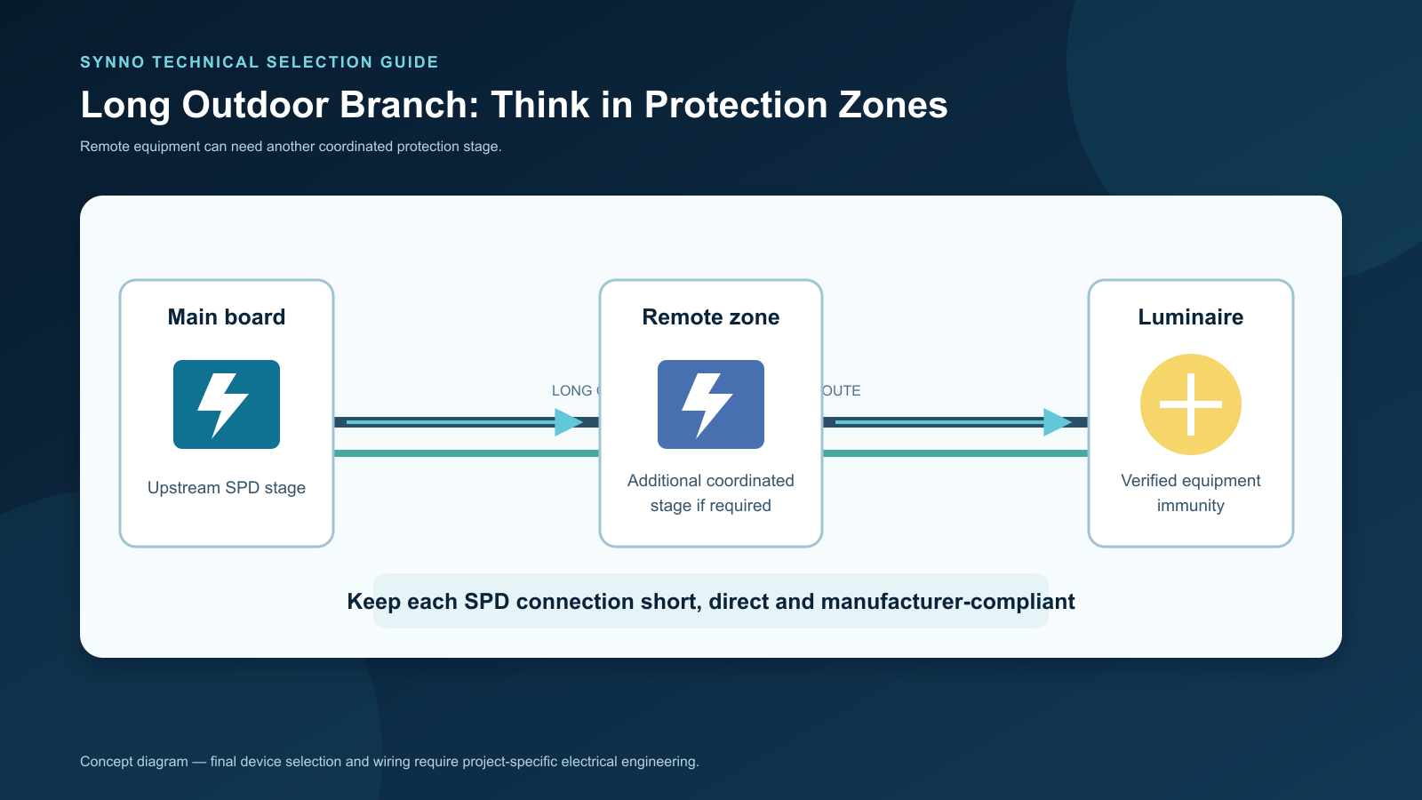
Outdoor lighting often spreads from a main building to gates, façades, pathways, signs, trees and remote parking areas. These conductors can couple transient energy and connect equipment located at different local potentials.
Distance also matters after an SPD is selected. The connection leads between the SPD, live conductors and protective conductor have inductance. During a fast current impulse, voltage develops across that inductance. The effective voltage at the equipment can therefore be higher than the device's Up value considered in isolation.
This is why SPD connections should be short, direct and arranged according to the manufacturer's instructions and applicable installation rules. Phoenix Contact's technical explanation of SPD connection length and effective protection level shows why long connecting leads can add substantial voltage during an impulse.
Do not confuse two distances:
- the short connection leads of the SPD itself; and
- the long feeder or branch between distribution points and luminaires.
The first affects the local clamping result. The second may justify an additional coordinated protection stage near a remote zone or equipment. The exact threshold and device arrangement must come from the electrical design, not a universal blog rule.
Avoid large cable loops
Route outgoing and return conductors together. Coordinate power, protective earth and control routes so the loop area is minimized. Where power and signal cables enter or leave a protected zone, evaluate them together; an unprotected control cable can become the remaining path into the driver or controller.
7. Earthing and Equipotential Bonding Complete the Current Path
An SPD does not make surge energy disappear. It changes the current path and limits the voltage difference seen by protected equipment.
That protective action depends on the earthing and bonding system. Long, looping or poorly connected conductors add impedance. Corroded connections, mixed-metal joints, undocumented local electrodes or disconnected protective conductors can undermine the intended result and create safety hazards.
For outdoor lighting projects, the electrical designer should confirm:
- the supply earthing arrangement;
- protective-conductor continuity to each Class I luminaire;
- equipotential bonding at remote cabinets and metal structures;
- connection of any local earth electrode into the overall design;
- conductor routing, cross-section and mechanical/corrosion protection;
- separation or bonding requirements associated with an external lightning-protection system;
- test and inspection records required by local regulations.
Never install an isolated earth rod beside a luminaire as an improvised “surge solution” without engineering review. During an event, separated earth references can create dangerous voltage differences across power, signal and metalwork.
8. AC, 24 V DC and Control Lines Need Separate Coordination
Mains-voltage outdoor luminaires
For 220–240 V or other mains circuits, the luminaire's input-stage immunity and the installation SPDs must be reviewed together. Class I and Class II luminaires may require different test and installation considerations; do not assume a metal housing alone identifies the protection class.
24 V low-voltage landscape systems
Low voltage does not mean “no surge risk.” The AC supply to the power unit, its DC output and long remote DC branches are different ports. Any SPD on the DC side must be suitable for the actual continuous DC voltage, polarity, fault current and circuit arrangement. The power supply's isolation and protective devices also matter.
Voltage drop remains a separate design issue. Oversizing a 24 V supply or raising its output to compensate for a long cable is not surge protection and can over-voltage luminaires near the source.
DALI, 0–10 V, DMX and other control wiring
Control interfaces can provide a path around power-side protection. Use only protective devices designed for the signal type, voltage, bandwidth and wiring topology. Coordinate cable shields and reference conductors according to the control-system and SPD manufacturers' instructions. Never connect a mains SPD directly to a control pair.
9. Three Outdoor Project Scenarios
Scenario A: small 24 V villa landscape
A weatherproof power-supply enclosure feeds several short garden branches. The designer reviews protection at the incoming AC supply, the power supply's port immunity and whether exposed DC branches need compatible local protection. The installer records polarity, branch length, cable size and joint locations.
Scenario B: hotel paths and remote bollard circuits
One distribution board feeds several zones across the site. A coordinated SPD arrangement, short panel connections, verified protective-earth continuity and accessible status indication are more maintainable than relying on the internal driver protection of dozens of bollards.
For installation issues beyond surge protection, see Synno's guide to common LED bollard-light installation mistakes.
Scenario C: façade lighting with DALI or DMX
Power and control cables cross between distribution zones and reach exposed façade equipment. The designer assesses both interfaces at zone boundaries and coordinates them with the building's lightning-protection measures. Protecting only the AC conductors may leave the control port vulnerable.
10. How to Investigate Repeated Outdoor LED Failures
Use a repeatable process rather than replacing parts one by one.
- Preserve evidence. Label failed luminaires and drivers by circuit and location. Do not discard the first failed units.
- Check the pattern. Were failures limited to the end of a branch, one phase, one remote cabinet or one control network?
- Inspect the SPD system. Record indicators, remote alarms, device part numbers, installation date and upstream protection.
- Inspect connections and moisture. Photograph terminals, joints, cable glands, condensation and corrosion before disturbing them.
- Verify the supply and protective conductors. A qualified electrician should test the installation and investigate temporary overvoltage or neutral faults.
- Compare damaged components. Input-stage damage across multiple drivers supports a different hypothesis from overheated capacitors or water-contaminated PCBs.
- Review the design boundary. Identify every power and signal conductor that enters the affected zone.
- Correct the system cause. Replacement luminaires alone are not a corrective action when the protection path remains unchanged.
11. Outdoor LED Surge-Protection Submittal Checklist
Before sample approval or a bulk order, request the following.
- Exact luminaire model, input voltage, driver and control-interface order code
- Applicable luminaire surge-immunity standard and test report or declaration
- Tested coupling modes, levels, polarities, ports and performance criteria
- Statement of any external SPD used during the luminaire test
- Single-line diagram showing the supply, distribution boards, remote zones and control cables
- Site lightning-risk assessment and external LPS information where applicable
- SPD type, Uc, Up, In, Imax or Iimp as applicable, modes and standards
- Backup protection, short-circuit coordination and disconnection method
- SPD connection drawing and maximum permitted lead lengths
- Status indication, remote alarm and replacement method
- Earthing and bonding drawing plus inspection/test records
- Separate review of AC, DC and signal-line protection
- Maintenance inspection interval and spare-device plan
Copyable RFQ wording
Please confirm the surge-immunity evidence for the exact luminaire, driver, input voltage and control configuration quoted. State the referenced standard and edition, coupling modes, test levels, polarities, ports, performance criteria and whether any external SPD was present during testing. We will coordinate this information with the project electrical engineer's installation-level SPD, earthing, bonding and lightning-protection design.
12. How Synno Can Support the Luminaire Side of the Review
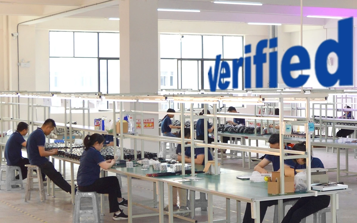
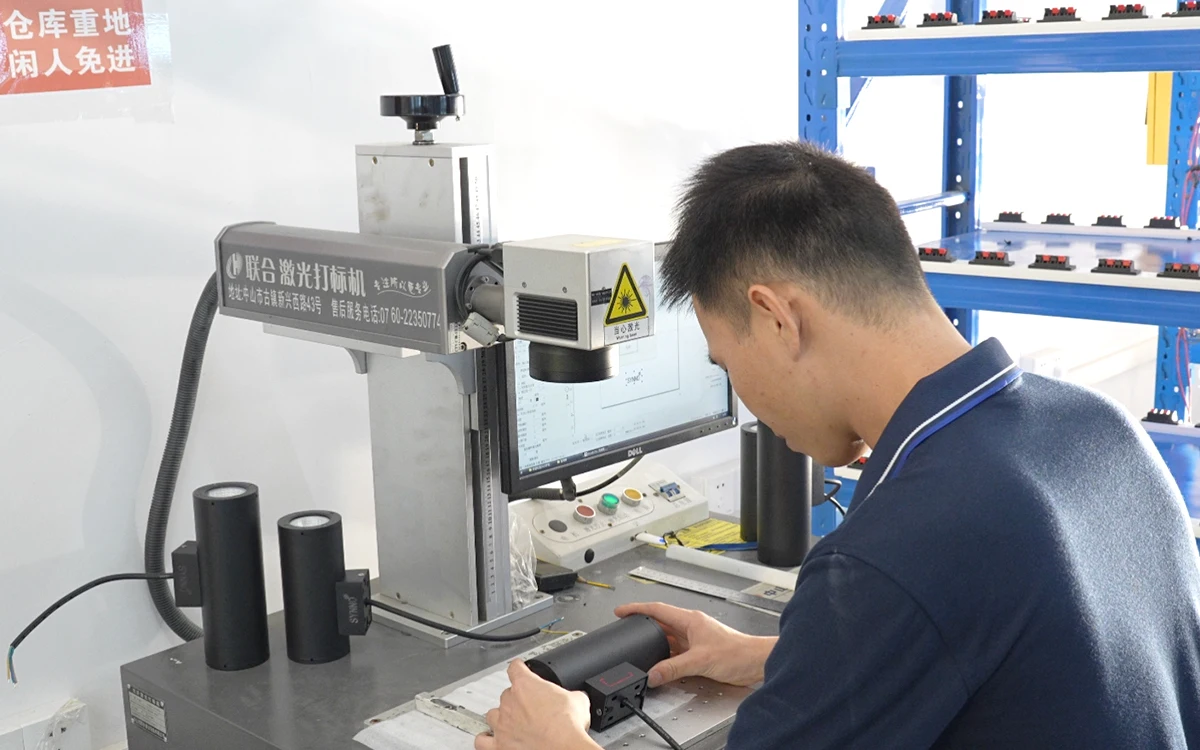
Synno Lighting manufactures outdoor luminaires for landscape, architectural and commercial applications, including garden spotlights, bollards, inground lights, wall lights and floodlights. Surge configuration can vary with the model, input voltage, driver and control option.
For that reason, a project enquiry should not begin with “Are all Synno outdoor lights 6 kV?” It should begin with the exact product family, quantity, voltage, control method, market and site exposure. Synno can then review which model-specific electrical data and available test evidence apply to the proposed order.
The installation SPD, earthing system and lightning-protection design remain the responsibility of the project's qualified electrical professionals. Luminaire evidence is one input to that design—not a replacement for it.
For applications involving broad-area or façade illumination, review Synno's garden and architectural LED flood lights. For pathway projects, review the LED bollard light range.
Frequently Asked Questions
Is a 6 kV LED light lightning-proof?
No. A 6 kV statement normally refers to a defined surge-immunity test configuration. It does not mean the luminaire can withstand a direct lightning strike, and it does not replace installation SPDs, earthing, bonding or a lightning-risk assessment.
Is an SPD required if the LED driver already has surge protection?
Internal protection and installation-level SPDs serve different coordination roles. Whether additional SPDs are required—and where—depends on the site, distribution system, equipment withstand levels and applicable regulations.
Should every outdoor luminaire have a local SPD?
Not automatically. A local stage may be appropriate for remote or exposed equipment, but the answer depends on coordination with upstream devices, cable length, supply arrangement, enclosure, maintenance access and the site protection concept.
Does a Type 2 SPD protect against a direct lightning strike?
Do not make that assumption from “Type 2” alone. Direct lightning-current duty, where required, is addressed within a wider lightning-protection design and may call for Type 1 or combined devices at specific locations plus downstream coordination.
Can the same SPD protect 230 V AC and 24 V DC lighting?
No universal SPD should be assumed suitable for both. The maximum continuous operating voltage, AC/DC rating, polarity, protection modes, fault conditions and installation standards must match the circuit.
Why can equipment still fail when an SPD indicator is green?
Possible reasons include an unprotected signal path, excessive connection lead length, poor bonding, a temporary overvoltage rather than a short surge, energy beyond the design case, wrong SPD selection or a non-surge failure such as moisture or overheating. The whole system must be investigated.
How often should outdoor lighting SPDs be inspected?
Follow the project maintenance plan, device manufacturer's instructions and local regulations. Inspection should also follow known severe events or unexplained equipment failures. Devices with status indicators or remote contacts make loss of protection easier to detect.
Conclusion
Surge protection for outdoor LED lights is a coordination task, not a single component claim.
The luminaire's surge-immunity evidence tells the project team what was tested in a defined configuration. Installation SPDs limit transient voltage and divert current at selected points. Earthing and bonding provide the intended current path. Cable routing and connection length influence the voltage that equipment actually experiences. Lightning-risk assessment determines the wider protection measures required by the site.
When these layers are documented together, contractors can diagnose failures more intelligently, buyers can compare quotations on equal terms, and maintenance teams can see when protection needs replacement. That is more valuable than simply asking for the largest kV number on a product sheet.
Need Model-Specific Electrical Data for an Outdoor LED Project?
Send Synno the product family, input voltage, driver or control option, quantity, destination market and site application. Our team can review the luminaire configuration and identify which available model-specific evidence should be coordinated with your electrical designer.
Request Project Support View Outdoor Flood Lights