The Professional Guide to LED Bollard Lights: Optical Cut-Off Engineering, Impact Resistance, and Pathway Illumination Design
Bollard lighting is one of the most visible—and most frequently misapplied—elements in an outdoor lighting system. A well-engineered bollard quietly guides pedestrians, reveals changes in elevation, defines the edge of a walkway, and establishes a consistent architectural rhythm. A poorly selected bollard produces uncomfortable glare, uneven pools of light, premature corrosion, and recurring maintenance problems.
For landscape architects, urban planners, and hospitality designers, the correct question is not simply "How many lumens does this bollard produce?" The more useful questions are: Where does the light go? Can pedestrians see the LED source? Will the housing survive real-world impact? Is the finish appropriate for irrigation, coastal air, and road salt? At Synno Lighting, with 15 years of manufacturing experience, our bollard platform spans 5–18W, heights from 300 to 1000mm, beam angles from 45° to 330°, and control options including DALI, 0/1-10V, and Triac — all built on aluminum bodies with 50,000-hour rated lifetimes.
1. The Dual Identity of Bollard Lights
A bollard light is simultaneously a luminaire and an architectural boundary element. During the day, its height, diameter, finish, spacing, and alignment influence how a pedestrian perceives the landscape. A row of bollards can reinforce the axis of a hotel entrance, separate a walkway from planted areas, or identify a plaza edge. At night, the same bollards must provide enough illumination for pedestrians to recognize paving changes, steps, curbs, obstacles, and other people.
Most architectural bollards are approximately 600–1000 mm high—below the standing eye height of most adults, yet the light source remains directly visible to approaching pedestrians, children, wheelchair users, and seated guests. The design challenge is to place useful light on the walking surface while keeping high luminance away from normal viewing directions. This requires three coordinated decisions: select the correct optical distribution, control brightness above the useful beam, and position bollards according to verified photometric data.
2. Cut-Off Optics: Keeping Light Below Eye Level
The Pedestrian Glare Problem
Glare is not determined by wattage alone. It is influenced by source luminance, apparent source size, background brightness, viewing angle, distance, and exposure time. A 7W LED concealed behind a properly designed reflector may appear comfortable, while a lower-power exposed LED can look painfully bright (Figure 1). This is why decorative bollards with clear diffusers or visible lamps often perform poorly in premium hospitality applications—they produce an attractive glowing object, but much of their light is emitted horizontally or upward instead of reaching the path.

Figure 1: Exposed LED source vs. deep-shielded cut-off optical chamber. The bollard should illuminate the path, not the pedestrian's eyes.
Understanding Cut-Off Angle & Asymmetric Distribution
A strong cut-off bollard concentrates useful luminous intensity between nadir (straight down, 0°) and approximately 60°–70°, minimizing intensity as the beam approaches horizontal. Where dark-sky requirements apply, the objective may include no measurable direct uplight above 90°. However, zero uplight does not automatically mean zero glare—a bollard can emit no light above horizontal and still be uncomfortable if a bright LED or reflector is visible at 75°–85°.
An asymmetric optical system uses a shaped reflector or lens to project more light forward and less behind the bollard (Figure 2). On a two-meter-wide walkway, a forward-throw optic can place peak intensity near the center of the path instead of directly around the bollard base—reducing the "bright spot and dark gap" pattern of simple radial optics while improving spacing efficiency.
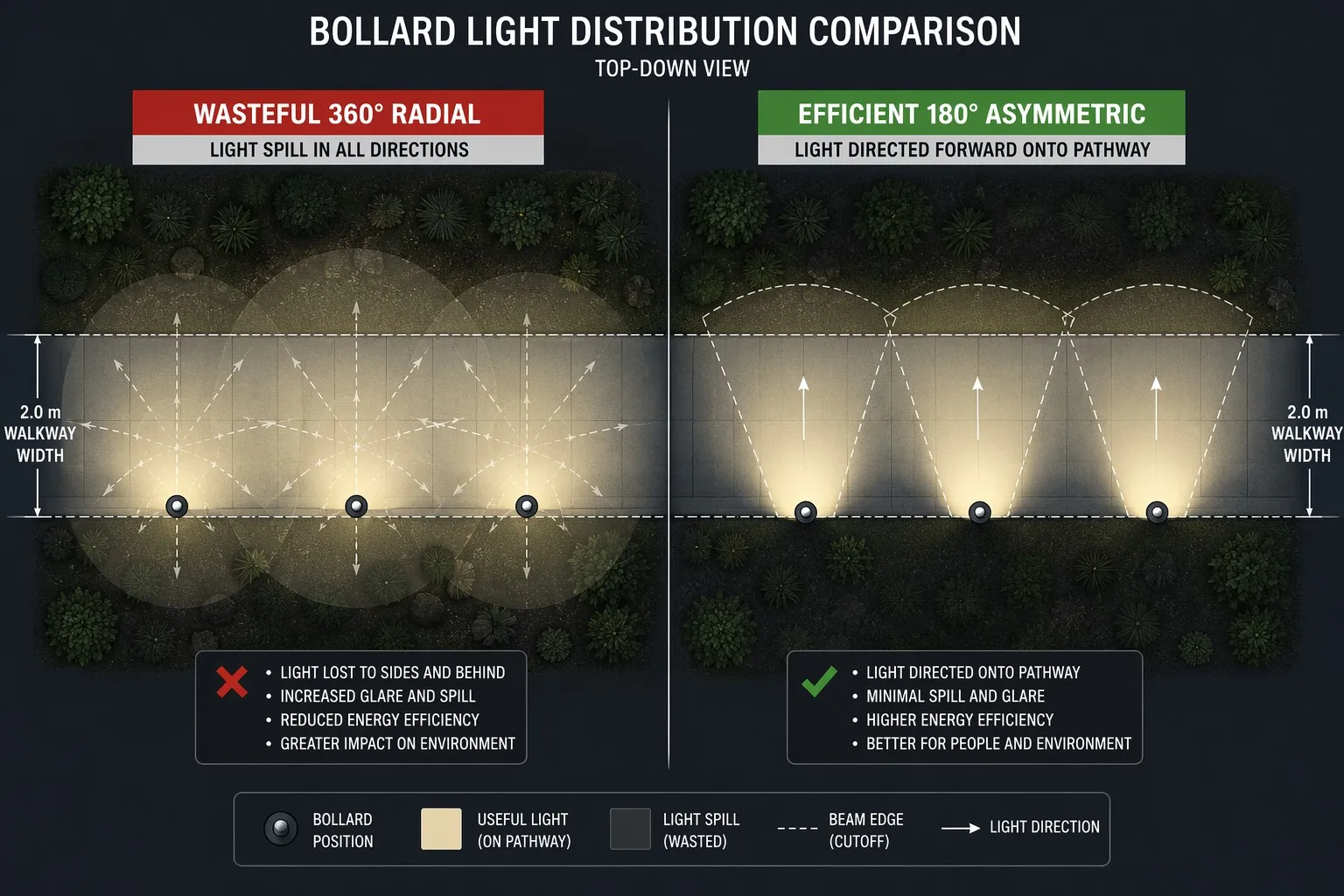
Figure 2: Radial 360° pattern wastes light into planting areas; asymmetric 180° forward-throw concentrates it on the pathway.
Louvers, Baffles, and Concealed Sources
Internal shielding is as important as the primary lens. Vertical louvers limit sideways visibility of the source. Horizontal blades establish a sharp upper cut-off. Deep-set LED modules use the physical depth of the optical chamber to prevent direct viewing at shallow angles. Matte-black internal surfaces absorb stray light, while precisely shaped reflectors redirect useful flux toward the path. Request an IES or LDT photometric file for the exact combination of LED, reflector, shield, diffuser, and louver being supplied.
3. Impact Resistance: Surviving the Real World
Outdoor bollards are exposed to bicycles, luggage carts, footballs, skateboards, cleaning equipment, vandalism, and landscape-maintenance machinery. Impact resistance must be evaluated as a system rather than as a decorative housing feature.
Controlled hotel gardens, residential developments, private courtyards, low-risk landscape areas.
Schools, transport environments, public plazas, urban parks — locations with greater vandalism risk.
IK10 is not a vehicle-collision rating. A slow-moving maintenance vehicle can impose far more energy than the enclosure impact test. Where vehicular contact is credible, use a separate protective barrier or structurally engineered traffic bollard.
Base-Plate Engineering
The base connection is commonly the weakest part of a bollard installation. A professional installation should include: a rigid base plate with adequate thickness, three- or four-point stainless-steel anchoring, a level concrete foundation extending below unstable topsoil, a cable entry that does not interfere with anchors, and drainage around the base. Four-point anchoring improves resistance to overturning from multiple directions. Anchor bolts must be positioned with a template before the concrete cures—oversized field-drilled holes and improvised washers are not substitutes for a coordinated foundation design.
4. Corrosion Strategy for Ground-Level Exposure
Bollards operate in the landscape splash zone. Irrigation water, fertilizer, soil chemicals, rain bounce-back, road salt, and cleaning agents accumulate near their bases—making the bottom 150mm of the fixture more corrosive than components installed higher on the building.
Powder-Coating System
For aluminum bollards, the coating process should be specified as a complete system: degreasing and surface cleaning, chemical pretreatment or conversion coating, controlled rinsing and drying, exterior-grade polyester powder application, correct curing time and temperature, and inspection for film thickness, adhesion, and discontinuities. A nominal dry-film thickness of approximately 60–80 μm is a reasonable project specification. ISO 9227 and ASTM B117 define controlled salt-spray test procedures for quality-control comparisons.
Marine-grade 316L is appropriate for coastal promenades, seaside resorts, swimming-pool surroundings, and environments exposed to chloride spray. Dissimilar metals must be isolated—stainless-steel fasteners in an aluminum body can create galvanic corrosion when moisture provides an electrolyte. Use nylon washers, isolating sleeves, and compatible sealants to break the galvanic path.
Weep-Hole Drainage
Any compartment designed to drain must include a clear exit path at its lowest point. Weep holes should not be blocked by grout, soil, mulch, sealant, or the mounting pad. A good bollard can have a drained outer column surrounding a separately sealed driver and optical chamber.
5. Pathway Illumination Design and Spacing Logic
Spacing-to-Height Ratio
A preliminary spacing of three to five times the mounting height is often useful during concept design. For example, 800–900mm bollards might begin at approximately 2.7–4.5 meters on center. Final spacing must be determined using the exact photometric file, pathway width, fixture setback, surface reflectance, orientation, mounted-light factor, and required uniformity. A wide symmetric optic may allow broader spacing but waste light outside the path; a controlled asymmetric optic produces a longer forward throw.
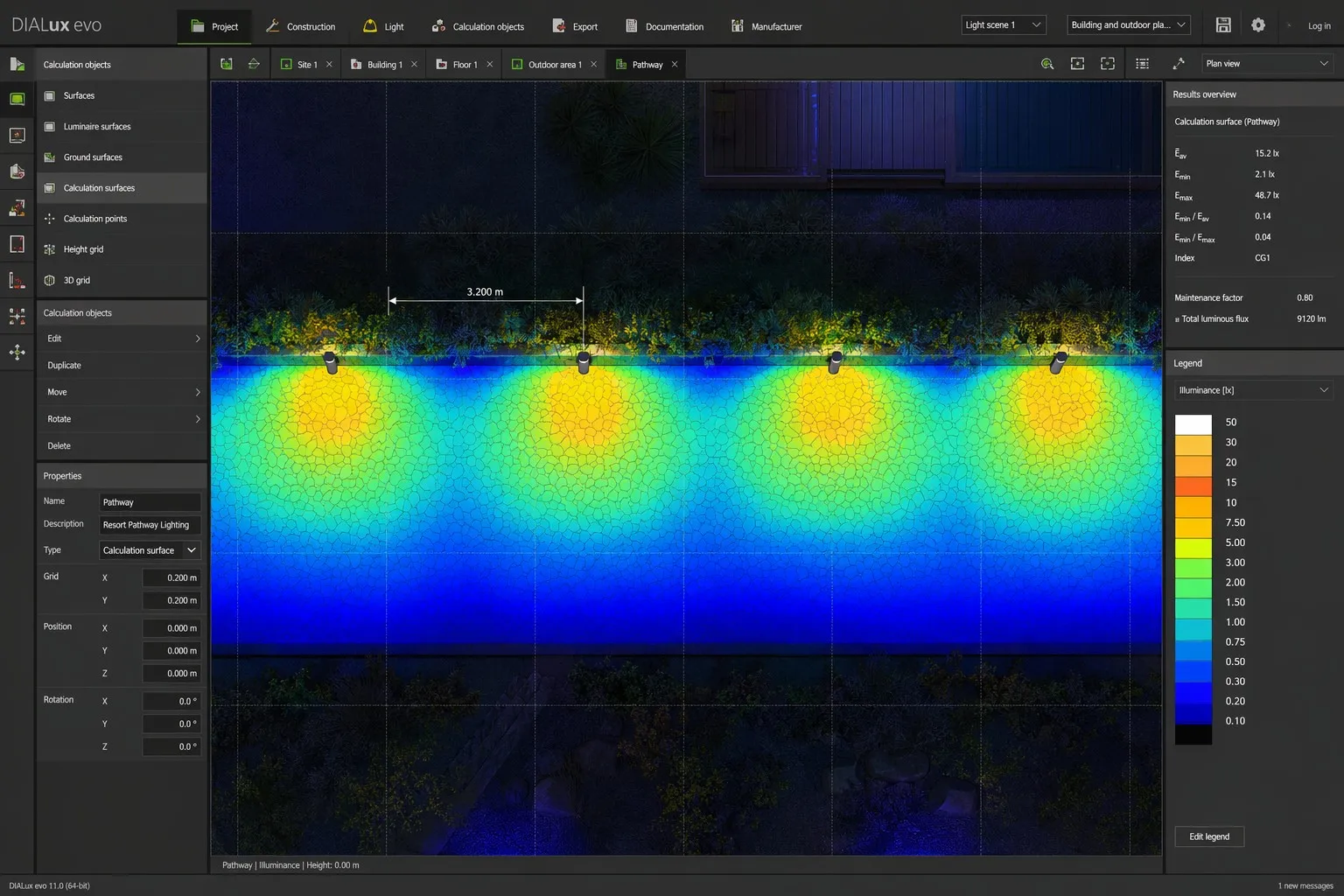
Figure 3: DIALux pathway calculation — asymmetric bollards at 3.2m spacing create smooth, overlapping light pools without dark gaps.
Illuminance Targets & Resort Pathway Example
The following values are practical concept-stage ranges:
| Application | Maintained Horizontal Illuminance |
|---|---|
| Quiet residential or garden path | 5–10 lux |
| Hotel, retail, or commercial walkway | 15–25 lux |
| Busy public plaza or transport-adjacent route | 30–50 lux |
Consider a two-meter-wide resort walkway with bollards installed along one side: mounting height 800mm, initial spacing 3.2 meters, shielded 180° forward-throw distribution, 2700K or 3000K CCT, matte black finish, astronomical schedule plus late-night dimming. The designer should test several rotations and setbacks—moving a bollard 150mm or rotating an asymmetric optic by a few degrees can materially change uniformity at the far edge.
6. Electrical Integration and Low-Voltage Safety
A 24VDC system can reduce electric-shock risk in accessible public areas, particularly when used with an appropriately listed or certified isolated SELV/Class 2 power supply. However, low voltage increases sensitivity to voltage drop.
For 100-meter-plus routes, consider dividing the path into shorter electrical zones, locating power supplies closer to the loads, feeding from both ends where permitted, increasing conductor size, or using a higher distribution voltage where code and equipment allow. For addressable control, DALI-compatible drivers allow grouping, scheduling, dimming, monitoring, and scene recall. A DALI subnet can address up to 64 control gear devices. Synno bollards support DALI, 0/1-10V, Triac, and ON-OFF control options across the platform.
7. Synno Bollard Light Engineering Platform
Synno Lighting's 2026 outdoor catalog includes aluminum-body pathway and bollard-style luminaires ranging from approximately 300 to 1000mm in height. Platform options include:
5–18W configurations across seven model families
45°, 120°, 180°, 330°, and 60°×135° distributions
SMD models: CRI 80 standard
COB models (SL-FL-L53, L102, L102S): up to CRI 90
AC220-265V / AC/DC 12-24V
DALI / 0-10V / Triac / ON-OFF
Matte black, white, grey, brown, custom RAL#
IP65/IP66, 50,000-hour lifetime, 3-year warranty
Representative models include the 1000mm SL-FL-B003 with 60°×135° distribution; 600mm SL-FL-L90 and SL-FL-L180R platforms; compact SL-FL-L265, SL-FL-L50, and SL-FL-L53 options; and the highly configurable SL-FL-L102/SL-FL-L102S families with multiple heights. IP, IK, and coating specifications should be confirmed for the exact selected model and project version.
8. Bollard Specification Checklist
Before approving a bollard light, require:
✓ Model-specific IES or LDT photometric file ✓ Verified beam distribution and source-shielding details ✓ Luminaire output, wattage, CCT, CRI, and color tolerance ✓ IP and IK test reports for the exact construction ✓ Housing alloy, wall thickness, and base-plate drawing ✓ Anchor template and foundation requirements ✓ Powder-coating pretreatment and film-thickness specification ✓ Salt-spray test method and acceptance criteria ✓ Driver type, surge protection, dimming protocol, and voltage range ✓ DIALux or equivalent calculation ✓ Maintenance-access procedure ✓ Project-specific warranty terms
Conclusion
Professional bollard lighting begins with optical control, not decorative appearance. The best system places light on the route, hides the LED from normal viewing angles, withstands realistic mechanical abuse, manages corrosion at ground level, and remains electrically stable across the full installation. Spacing rules and wattage schedules can support early planning, but they cannot replace model-specific photometry and a coordinated site calculation. A successful design combines cut-off optics, asymmetric distribution, appropriate IK resistance, reliable base anchoring, exterior-grade finishes, voltage-drop engineering, and intelligent controls.
Project Support — 15+ Years of Manufacturing Expertise
Planning a hospitality, landscape, or public-realm project?
Contact Synno Lighting for a professional DIALux layout simulation, model-specific optical selection, and OEM/ODM bollard lighting development.
Disclaimer: Specifications must be confirmed for the exact model and project version. IP, IK, and coating test reports should be model-specific. Warranty terms are project-dependent.