The Underground Light Installation Playbook: Pre-Installation Sleeves, Drainage Engineering, and Cable Routing for Zero-Callback Projects
Two identical LED inground lights leave the same factory. They use the same housing, LED, driver, seals, cable gland, and optical assembly. The first is installed in a paved commercial plaza. Six months later, moisture appears behind the lens and the fixture fails. The second is installed at a hotel entrance. Five years later, it is still operating normally.
The difference may not be the luminaire. It may be everything surrounding it. At the failed location, concrete was poured directly against the fixture body. The excavation became an isolated water pocket. At the successful location, the contractor installed a correctly sized pre-installation sleeve, connected the aggregate bed to the site drainage system, used wet-location wiring components, and documented the complete installation before closing the paving.
This is the central lesson of professional inground lighting: the luminaire may be manufactured in a controlled factory, but its service environment is manufactured on the construction site. For contractors, landscape architects, and project managers, four installation decisions largely determine long-term reliability: the pre-installation sleeve, the drainage path, the cable waterproofing strategy, and final commissioning. At Synno Lighting, with 15 years of manufacturing expertise, the SL-GR1D series (Figure 1) is engineered with a brushed stainless steel faceplate, tempered glass lens, triple-COB optical assembly, and IP68 compression gland—but even the best-engineered fixture depends on a well-engineered site.
All dimensions in this guide are practical starting points — not universal instructions. Final installation must follow the approved luminaire drawing, structural requirements, site geotechnical conditions, drainage design, electrical code, and local authority requirements.
1. Why Installation Defines Inground Light Longevity
An inground luminaire operates in one of the most demanding environments in architectural lighting. Unlike a wall light, its enclosure is surrounded by soil, aggregate, concrete, pavers, or asphalt. Rainwater moves toward it by gravity. Irrigation systems repeatedly wet the surrounding ground. Vehicles, maintenance equipment, pedestrians, freeze-thaw cycles, and thermal expansion introduce mechanical stress.
The installation must manage: surface water, groundwater, condensation, capillary water ingress, cable-joint failure, concrete movement, differential settlement, vehicle loading, glass temperature, improper leveling, and inaccessible junction boxes. An IP rating is not a drainage strategy. The project team should separate three responsibilities: the manufacturer supplies a luminaire suitable for the application; the designer creates the sleeve, loading, drainage, wiring, and control details; the contractor builds those details accurately and records deviations. When one party assumes another handled drainage, callbacks begin.
2. Pre-Installation Sleeves vs. Direct Burial
2.1 Why the Sleeve Is the Commercial Standard
For permanent commercial hardscape, a pre-installation sleeve is normally preferable to embedding the finished luminaire directly in concrete. The sleeve establishes the opening before paving, protects the luminaire from construction damage, separates the fixture body from concrete movement, creates controlled clearance around the housing, provides a repeatable finished elevation, maintains access to the cable entry, and allows future fixture removal and replacement. Without a sleeve, the concrete installer may use the actual luminaire as formwork—exposing the finished housing, lens, cable, and seals to cement paste, impact, vibration, and construction traffic.
A fixture expected to last years should not be installed in a way that makes routine replacement a demolition project.
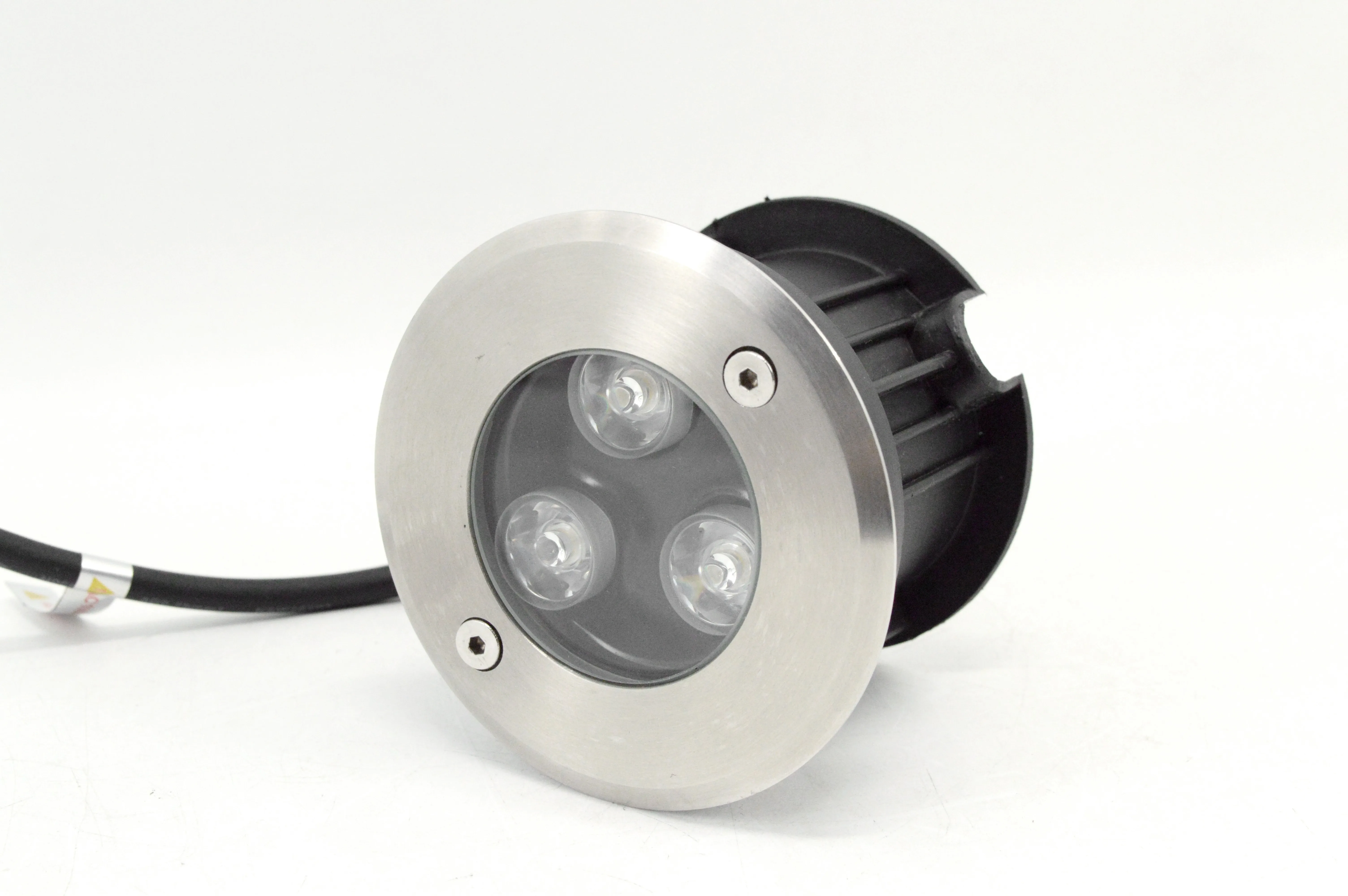
Figure 1: SL-GR1D — the fixture that goes into the sleeve. Brushed stainless steel faceplate, triple-COB optics, and integrated heat-dissipation fins.
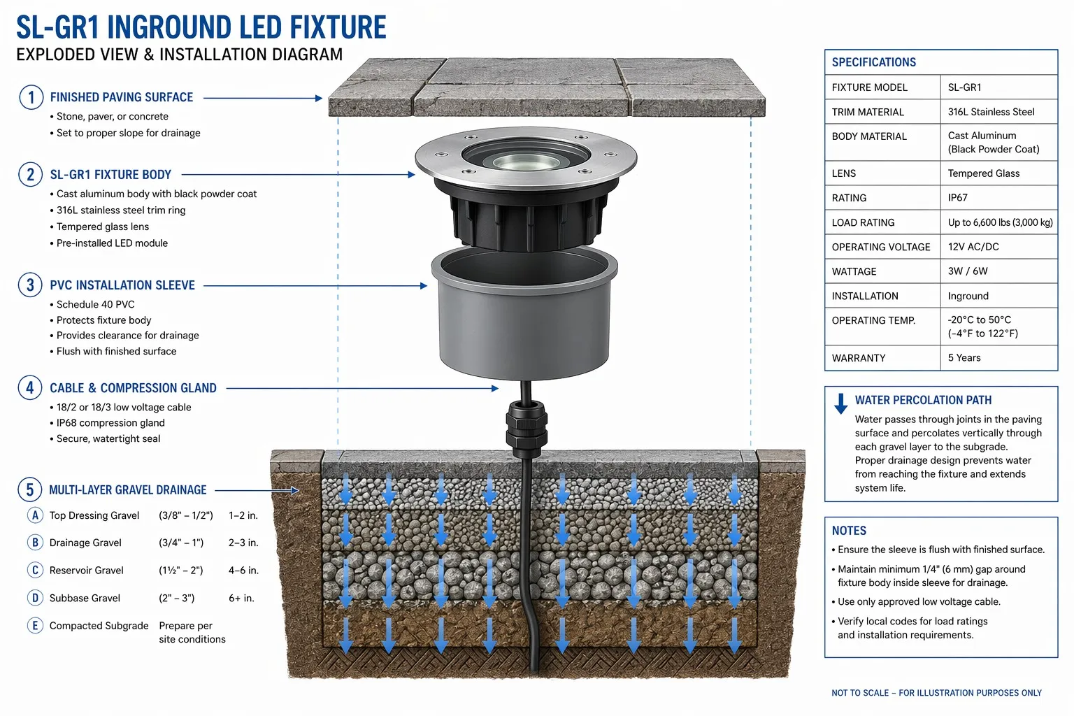
Figure 2: Exploded assembly view — fixture, sleeve, cable gland, and multi-layer gravel drainage system.
2.2 PVC Sleeves
PVC is widely used because it is corrosion-resistant, lightweight, easy to cut, economical, and electrically nonconductive. A PVC sleeve works well in pedestrian paving when the surrounding construction—not the sleeve wall alone—carries the design load. However, PVC can deform under construction pressure or heat. A thin-wall pipe should not be assumed to provide structural support beneath vehicle wheels.
2.3 Stainless Steel Sleeves
Stainless steel housings provide higher mechanical stability and precise finished dimensions for high-end stone paving, coastal projects, and public plazas. The designer should specify grade, wall thickness, weld treatment, passivation, and isolation from dissimilar metals. A stainless sleeve must not become a closed metal bucket—if its base is sealed without a designed drain connection, it preserves water around the luminaire more effectively than an open soil excavation.
2.4 Clearance Between Sleeve and Fixture
A common baseline is a sleeve internal diameter approximately 10–15 mm larger than the fixture's maximum body diameter. Too tight, and the sleeve binds the fixture during installation, prevents future removal, and transfers concrete movement into the housing. Too loose, and the fixture may tilt, collect debris, or create an annular water pocket. Use the manufacturer's centering ring or mounting flange where provided.
2.5 Sleeve Elevation and Finished Grade
A common pedestrian-area starting point is to set the sleeve rim approximately 2–3 mm below the finished paving plane. If the fixture is too high, it becomes a trip hazard; if too low, the lens collects water, dirt, and cleaning chemicals. For drive-over applications, finished elevation and load transfer must follow the load-rated installation detail. Use a laser level and a physical sample of the final paver or stone. "Approximately flush" is not a measurable installation instruction.
3. Drainage Engineering: The Gravel Base That Makes or Breaks the Project
3.1 Why an Isolated Hole Fails
Water moves toward an inground fixture from rainfall, surface runoff, irrigation, perched groundwater, condensation, and leaking water services. An excavation filled with gravel does not automatically drain. If the surrounding soil is clay or the hole has no outlet, the gravel simply becomes a reservoir. The objective is to create a continuous percolation path leading water away—not to place stones beneath the luminaire and hope.
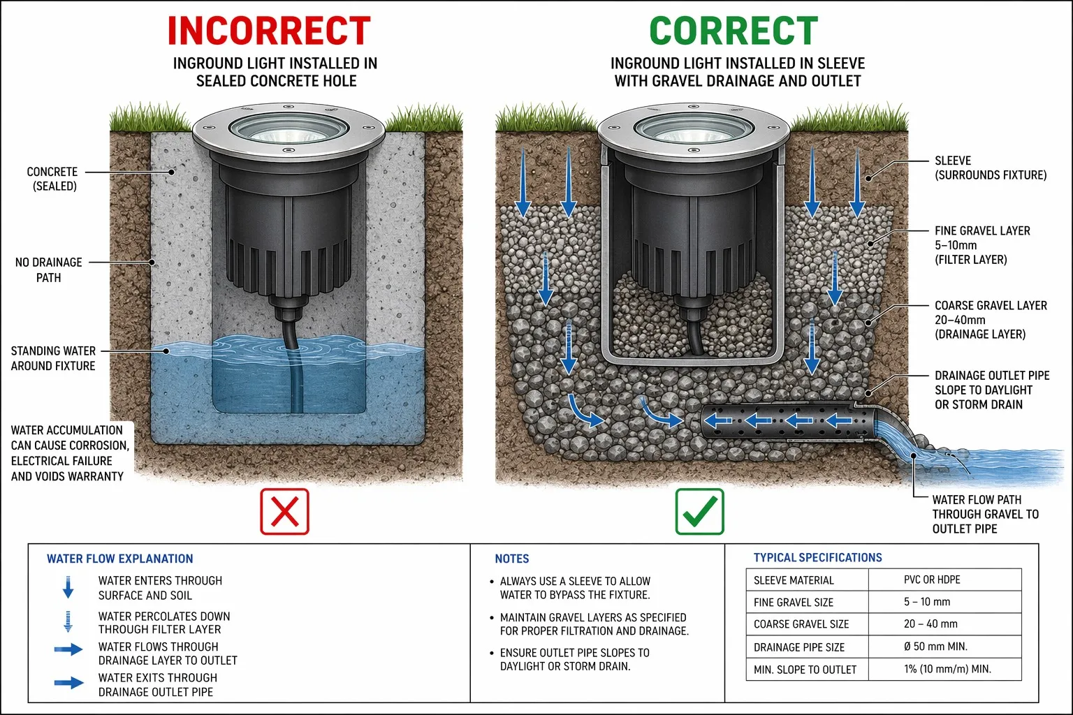
Figure 3: Side-by-side drainage comparison — a sealed hole accumulates water, while a connected gravel bed channels it away.
3.2 Recommended Aggregate Layering
A practical starting detail: a bottom drainage layer of 150–200 mm depth using clean, coarse aggregate (approximately 20–40 mm, no fines) for storage volume and bulk drainage; a middle leveling layer of approximately 50 mm using smaller clean aggregate (5–10 mm) for a controllable bed beneath the sleeve. Depths must be increased where required by poor soil permeability, high rainfall, freeze-thaw conditions, or high groundwater. Aggregate should be washed and angular—soil-contaminated gravel quickly loses permeability.
3.3 Connect the Base to Site Drainage
The gravel base must connect to the broader civil drainage concept. Before excavation, resolve: where does collected water discharge? Is the receiving drain lower than the fixture? Can the drain surcharge during a storm? A perforated drain should have suitable fall, cleanouts, and an approved discharge location.
IP68 certification describes enclosure protection under defined test conditions — do not assume it permits permanent submersion below the water table. If groundwater is permanent, relocate the luminaire, raise the installation, engineer drainage/sump protection, or select equipment specifically approved for continuous submersion with written manufacturer approval.
4. Cable Entry Waterproofing and the Anti-Siphon Principle
4.1 Underground Raceways Are Wet Locations
Contractors often assume that conductors inside conduit remain dry. Underground raceways can collect condensation and water through joints, boxes, and temperature changes. Use cable, conductors, boxes, glands, and splice systems suitable for the actual environment.
4.2 The "Straw Effect"
Water does not need to pass through the front lens to reach a fixture. A damaged or unsealed cable end can admit water between conductors, fillers, shields, and jacket layers. Pressure differences and capillary action can move moisture along internal paths—the cable behaves like a straw, transporting water from a remote junction toward the luminaire. This is why replacing only a front gasket may not correct a recurring moisture problem.
4.3 Three-Layer Defense
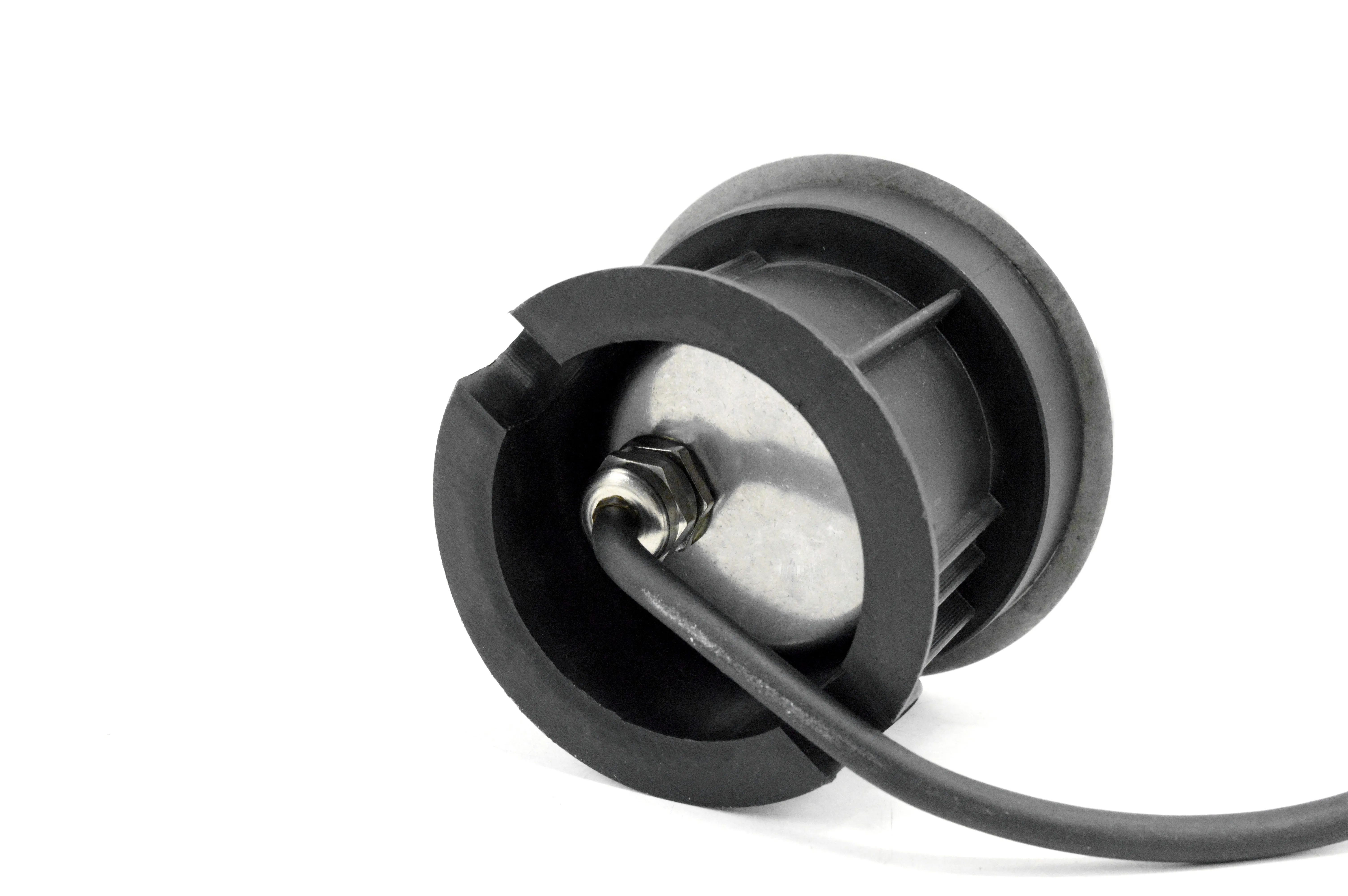
Figure 4: Layer 1 — the SL-GR1D's IP67 metal compression gland. Torque to the manufacturer's specification, not by feel.
Layer 1 — IP67 Compression Gland: The gland (shown on the SL-GR1D in Figure 4) must match cable outer diameter, jacket material, entry thread, environmental rating, and temperature range. Use the torque value provided for the approved luminaire and gland. Too little torque leaves an incomplete seal; excessive torque damages the seal, thread, or cable jacket. Do not apply sealant to gland threads unless the manufacturer requires it.
Layer 2 — Factory Cable Termination: Where the fixture uses an internally potted cable termination, the encapsulation provides a secondary barrier against moisture migration. Do not open a factory-sealed fixture or add field epoxy unless the manufacturer expressly authorizes the procedure.
Layer 3 — Drip Loop: Before a cable enters an above-grade junction point, form a downward U-shaped loop. Water traveling along the cable exterior reaches the low point and drips away instead of following the cable into the enclosure.
4.4 Junction-Box Position & Conduit Routing
Whenever practicable, locate serviceable junction boxes above the expected water level, outside the drainage pocket, away from irrigation emitters, and where they remain accessible. Keep electrical conduit separated from irrigation lines. Install detectable warning tape above buried electrical routes and use trace wire or electronic markers where required.
5. Final Leveling and Structural Preparation
A "drive-over" luminaire is not automatically suitable for every driveway. Verify static load rating, dynamic wheel-load rating, contact area, vehicle type, speed, turning and braking forces, fixture orientation, and surrounding concrete detail. The sleeve and surrounding structure must transfer load as designed—the fixture trim should not be left unsupported above a void.
Trafficable-area specification: Correct leveling and sleeve support cannot make a pedestrian-only luminaire suitable for vehicle traffic. Before approving products for walkways, private driveways or service routes, review our drive-over vs. walk-over LED inground light load-rating guide. It explains how to separate IP, IK and rated load, define the vehicle condition, and request model-specific test evidence before installation.
Before final tightening: clean the sleeve, remove aggregate and concrete debris, confirm drainage openings are unobstructed, check the cable for damage, center the luminaire, verify the trim elevation with a straightedge, confirm the lens does not rock, tighten fasteners in the specified sequence (note the two hex-head screws on the SL-GR1D faceplate in Figure 5), and protect the lens until construction is complete. Do not use the fixture trim to correct a badly positioned sleeve.
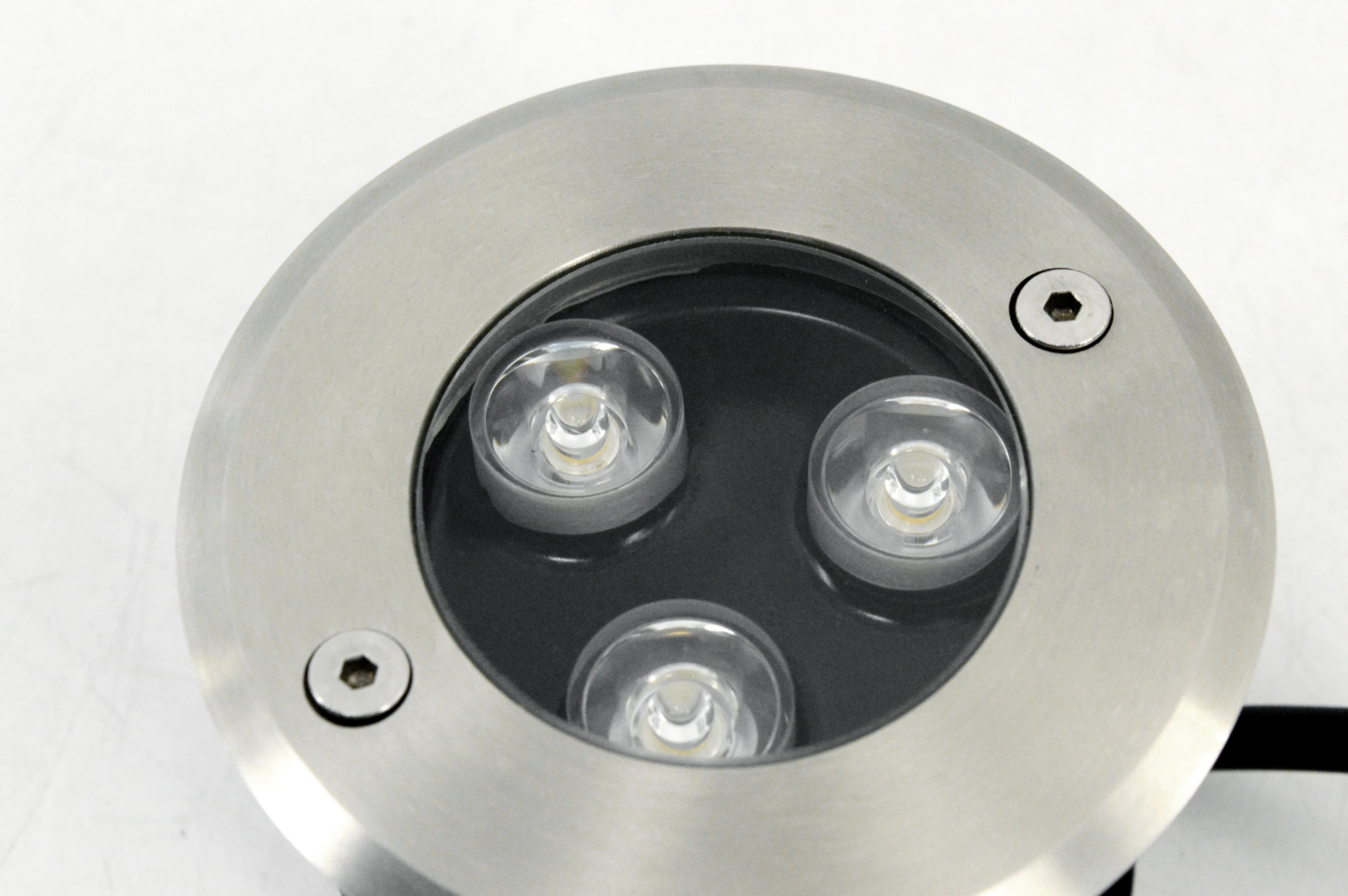
Figure 5: SL-GR1D faceplate — tighten the two hex-head screws in the specified sequence for a level, water-tight seal.
6. Commissioning and Final Verification
6.1 Test Before Backfill and Paving
Power and test every fixture before closing the installation. Verify correct circuit, supply voltage, polarity for DC systems, protective grounding, driver compatibility, dimming response, control addressing, beam direction, CCT consistency, visible flicker, water-tight cable connections, and physical stability. Correcting an aiming or wiring error while the sleeve is open takes minutes; correcting it after stone paving is complete may require an entire crew.
6.2 Pre-Backfill Inspection Hold Point
Create a formal inspection hold point. The supervisor signs off on: sleeve dimensions, sleeve elevation, drainage depth, drain connection, conduit route, junction-box accessibility, cable protection, gland installation, and fixture operation. Do not permit paving to proceed because the electrical contractor "will test it later."
6.3 Operating Test, Night Commissioning & As-Built Documentation
Operate fixtures at full output for at least two hours before final acceptance. Aim inground lights after dark—check for glare toward entrances, light spill into guestrooms, spill into roadways, uneven façade illumination, excessive hot spots, and color inconsistency. Photograph every installation before backfill with fixture ID, model information, circuit number, junction-box location, conduit direction, drain outlet, sleeve depth, cable route, and measuring tape reference. Documentation is essential for future maintenance, cable replacement, warranty evaluation, drain cleaning, and avoiding excavation damage.
7. Common Installation Failures — and How to Prevent Them
Concrete shrinkage and thermal movement act directly on the housing. Prevention: use the approved pre-installation sleeve, keep concrete out, brace and cap during the pour.
Under-tightening leaves an incomplete seal; over-tightening damages the cable. Prevention: tighten only to the documented torque specification.
The excavation becomes a stone-filled bucket. Prevention: test soil percolation, connect the aggregate bed to site drainage.
A non-submersible splice sits in a wet sleeve. Prevention: use listed wet-location splice systems, keep junction boxes accessible.
Water and sediment collect on the lens. Prevention: coordinate every finish layer, set sleeves with a laser, use a sample paver.
Continuous submersion exceeds design limits. Prevention: review seasonal groundwater data, relocate or engineer drainage.
8. Zero-Callback Field Checklist
Before Concrete
✓ Approved fixture and sleeve drawings on site ✓ Sleeve diameter and depth verified ✓ Paver and bedding thickness confirmed ✓ Load rating confirmed ✓ Drain outlet identified ✓ Percolation test completed ✓ Conduit route coordinated ✓ Junction boxes accessible ✓ Sleeve braced, capped, and surveyed
Before Installing the Fixture
✓ Sleeve clean and round ✓ Drainage openings clear ✓ Water test passed ✓ Cable inspected ✓ Correct gland and seal installed ✓ Wet-location splice system available ✓ Supply voltage verified ✓ Fixture model matches approved schedule
Before Backfill or Paving
✓ Every fixture energized ✓ CCT and beam verified ✓ Dimming tested ✓ DALI or control addresses documented ✓ Gland installation inspected ✓ Drainage photographed ✓ Conduit route photographed ✓ As-built measurements recorded
Before Handover
✓ Two-hour operating test completed ✓ Night aiming completed ✓ Lens and trim cleaned ✓ Fastener torque checked ✓ Spare fixtures and accessories labeled ✓ Drain and junction-box locations recorded ✓ Maintenance instructions delivered ✓ Warranty documentation completed
Conclusion
Reliable inground lighting is not achieved by purchasing an IP68 fixture and placing it in a hole. It is achieved by engineering the entire installation environment: the pre-installation sleeve separates the luminaire from concrete movement and preserves replaceability; the aggregate system creates a percolation path only when it connects to a functioning outlet; the cable gland, factory termination, wet-location splice, drip loop, and accessible junction box work together to resist moisture; correct conduit routing protects the electrical system; accurate leveling prevents standing water and trip hazards; and pre-backfill testing with as-built documentation prevent expensive callbacks.
Synno Lighting manufactures LED underground and landscape luminaires—including the SL-GR1D series shown in this guide—in Jiangmen, China, with product options for architectural, hospitality, commercial, and outdoor projects. But even a well-engineered luminaire depends on a well-engineered site. The most effective time to prevent an underground-light failure is not after moisture appears behind the lens — it is before the concrete is poured.
Project Support — 15+ Years of Manufacturing Expertise
Planning an architectural landscape or commercial hardscape project?
Contact Synno Lighting for product selection, installation coordination, photometric support, and OEM/ODM underground lighting development.
Technical disclaimer: All dimensions are starting points. Final installation must follow the approved luminaire drawing, structural requirements, site geotechnical conditions, and local codes.